It depends on context. When it appears on a switch or relay it means Normally Closed. If it appears on a circuit board or wiring diagram, it usually means that the terminal is Not Connected. It’s fairly common for connectors to be used that have more pins available than are actually required. The unused pins are labelled NC.
That having been said, I checked the schematics on Github but couldn’t find the B1 version. The non-B1 version has that connector labelled PA15/GND/3.3V.
yeah, I’ve never see anything but an already compiled binary for the TFT. i’m going to bypass the daughterboard and plug the sensor directly to the TFT with the OEM cable, I’ll just leave the bottom off to try it
Tried it. didn’t work. I think there’s no continuity on the middle wire between the plugs. I’ll have to look at it later my tools are too big to probe the tiny wires and sockets. and it’s in an awkward location heh. I already tied the wires into a nice tight harness for the upper carriage
Update: the cable is good. It was just easier to pull the pins and test it
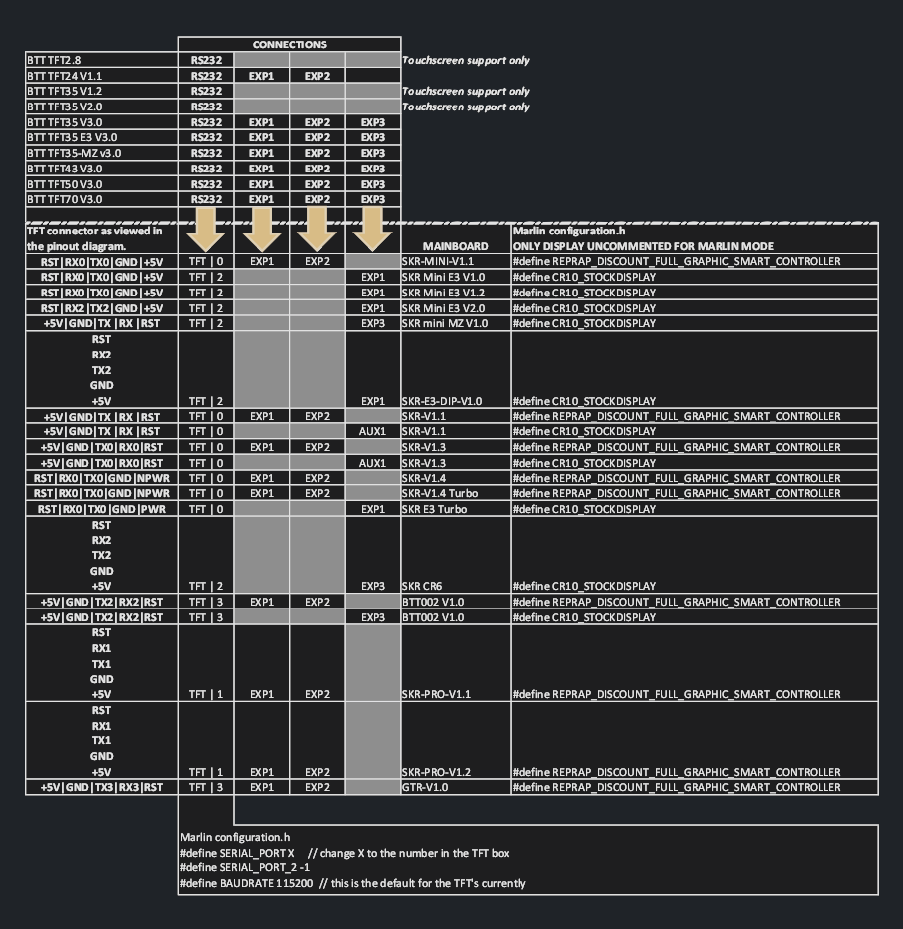
Was reading this
It’s not clear to me if the wire order has to change I’m unsure if it’s the socket in the TFT he is representing or the end of the plug the socket in the TFT is 3 connection and so is the plug on the cable.
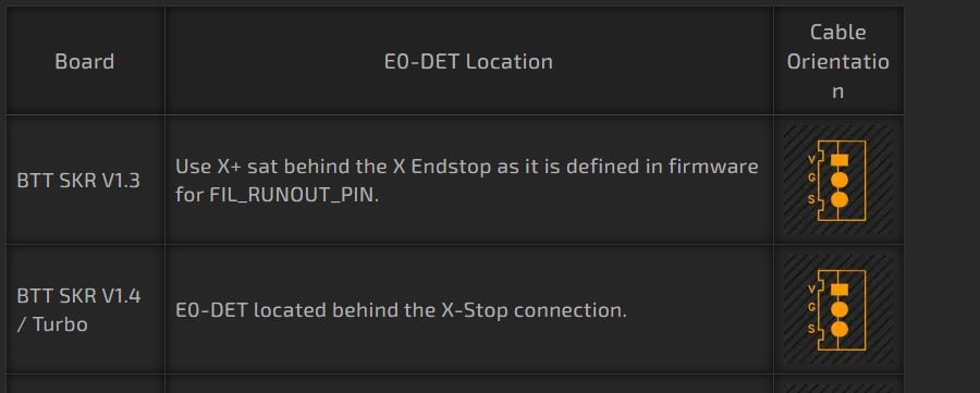
That’s a really great walk through. To bad it doesn’t mention SKR 1.3, 1.4 …
Is it possible that on the SKR 1.4 the voltage pin power is also disabled like the E3 Mini 1.1, 1.2?
causing you to have to use the PT-DET, or X+ like the SKR 1.3?
Thanks
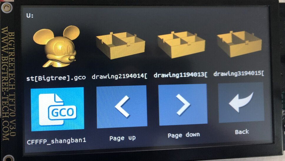
I found this earlier today and grabbed the Cura plugins so the model viewer works in print file selection but I didn’t see the config.ini file. Also, I know there’s power at the sensor but I haven’t been able to test for pulses, I’m afraid of shorting it I need a better way to probe the little pins.
well, it works now. it seems. it’s just finishing a small print I’ll try stopping the filament on the next thing but it’s never run before with the smart sensor on.
So I put the wires back the way they were from the factory and still no good. but I did determine that the sensor provides a pulse. So I had purchased a complete hot end earlier as a spare and it came with the daughterboard that all the connections go into on the rear of the printer so I swapped it out (I know where all the wires go now heh) and the sensor seemed to work now… I don’t see anything that would cause this little board to not work so maybe there was just something on it not connected tight enough? Too many of these little slip-on connectors on these printers. anyway, it’s working now… I seem to be burning through my spare parts too quickly though.
There was one included in the hot end I bought, I was going to keep as spare. That ones in the printer now and working. I didn’t put the old one back in to see if that was really the problem, I just tried it because I seemingly tried everything else and it seemed like the original wiring was not a mistake.
Found it. you can make changes to the TFT firmware through the config.ini file., Just edit the entry you want and boot the machine with that on an SD card and it’ll make the changes you selected.