I was printing some stuff with carbon PETG and Filaflex 82a and was getting some curling on overhangs so I decided to go a bit of an adventure trying to design a new cooling duct for the Micro Swiss direct drive on my printers.
I thought about printing one of the Hero Me or various other cooling systems but I wasn’t thrilled how many parts they print in and how some of them if you need to take off the fan shroud your BLTouch mount gets removed with it. I want the BLTouch to always stay attached so that I don’t have to check the Z offset every time I pull the fans off.
Version 1: Single 4020, duct in front of nozzle and was too close to heat block and started to melt

Version 2: Single 4020, moved the duct to the back, rotated the fan 180*, more clearance for the end of the duct so it seems to be far enough away not to melt, but it was too directional from one side

Version 3: Dual 4020 with opposing ducts, modified mount to have more than one bolt, seems to cool better but is way more bulky. Yet to be determined if I stick with this one or move on to version 4. So far this one seems to have better coverage for cooling so it isn’t directed only at one side of the model

This is the pile of attempts. I had a few print failures because resin is a finicky beast when it comes to supports etc.
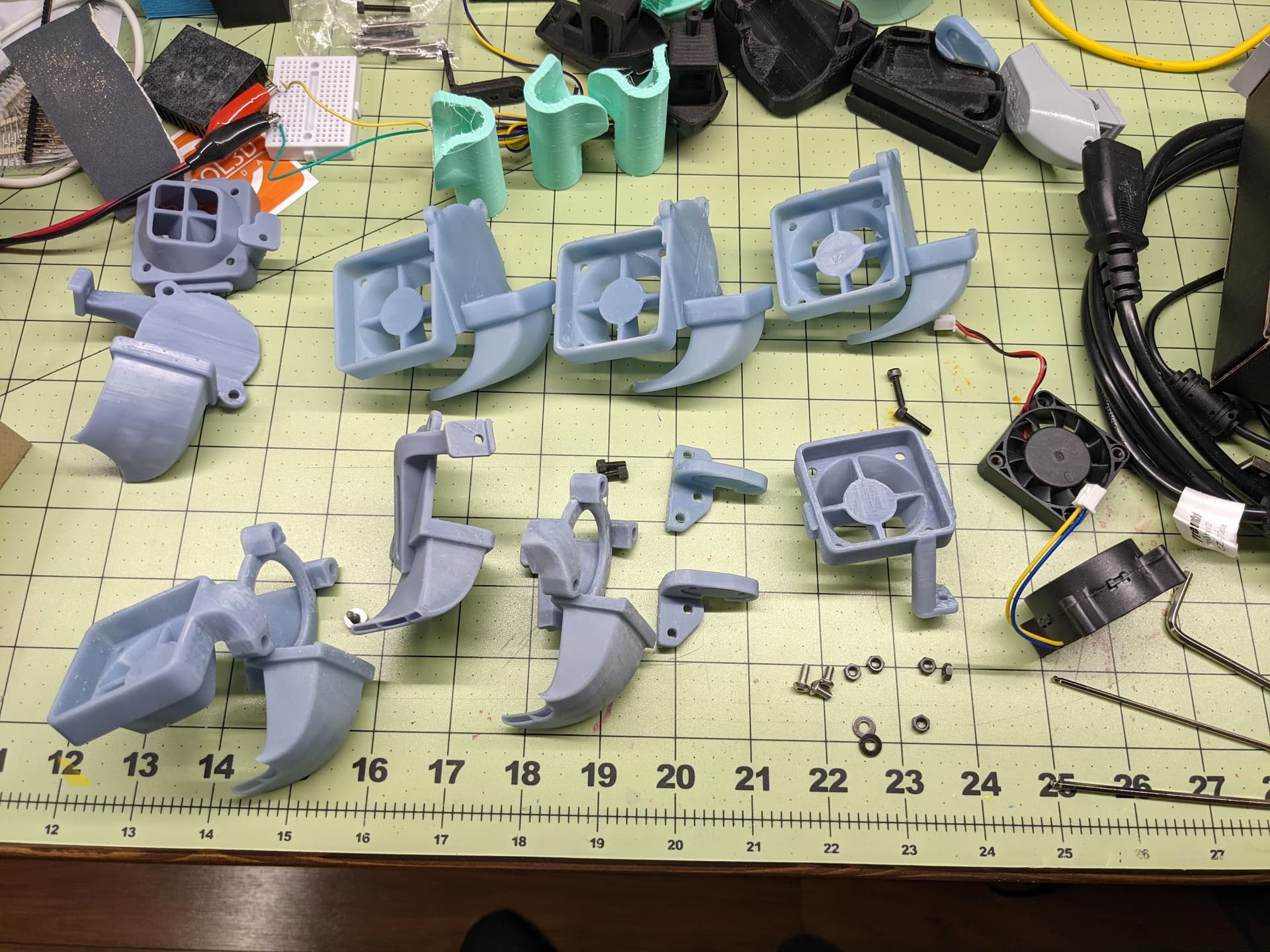
Version 3 needed to be split up into 3 parts because it got too big to fit on the build plate in one piece so I chopped the model and added some slots and grooves to put the parts together. It also made supports and slicing easier since I could orient each piece separately.


I printed it out of resin for a few reasons.
- I wanted to.
- I thought the resolution of resin would make for smoother air flow with almost invisible layer lines
- This shape would have been an absolute nightmare to do with supports on FDM. Just for fun I sliced it in Cura and it was going to be like 26 hours instead of 5.5 on the resin printer
- The walls on the ducts are about .75mm thick and the grate at the top of each duct is .5mm walls which would be pushing it for a good FDM print
- It seemed like a good experiment to try printing a functional part with resin. Until now I haven’t been using it for that but have some mechanical art projects I want to make that will need resin gears and cams and fun stuff like that.
Here’s a before and after of a Benchy printed with Recreus Filaflex 82A. The overhang on the bow was a big problem area since each layer was curling upward causing a lot of deformation. Feel free to make fun of how bad the stringing is but this stuff prints like snot and I really don’t think I’ll be able to get rid of it. Basically I’m choosing to live with stringing to get more consistent extrusion.
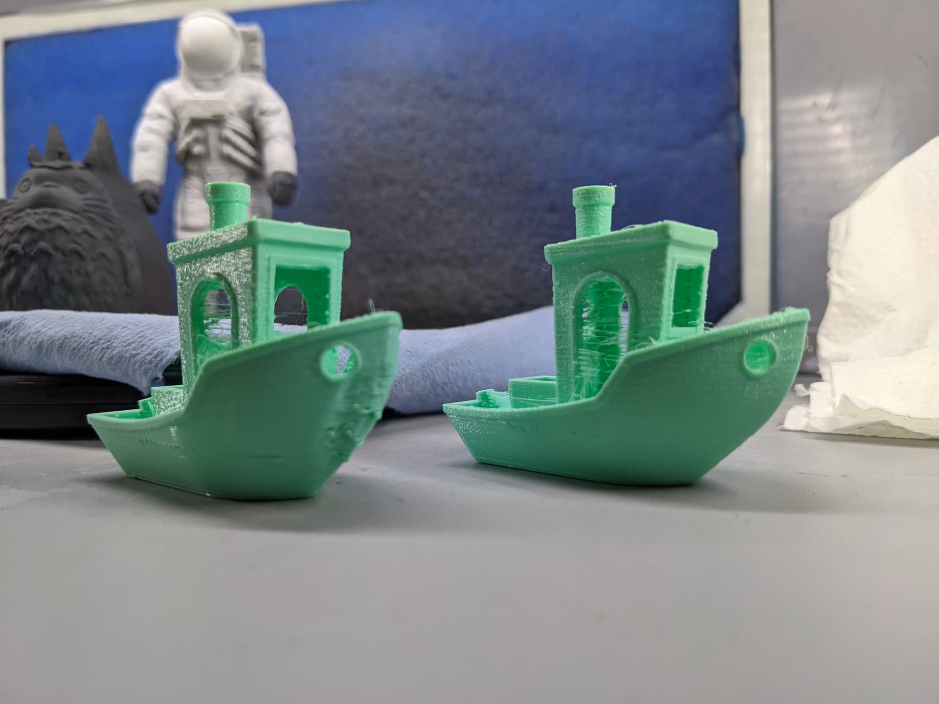
Printed in Monocure Tuff for anyone that cares.
Things I learned:
- I don’t understand fluid dynamics
- Printing large flat surfaces with resin is annoying to try to keep them actually planar
- Resin is not cheap to prototype with
- When you think you have enough supports, add a whole lot more light ones
At some point I want to try blowing my smoke machine around the fans so I can actually watch what the flow coming out looks like to try to reduce turbulence and improve coverage
My next attempt I would also like to design in a quick release system and improve access to the nozzle so I can wipe gunk off while printing or ideally be able to easily nozzle change without removing the duct.

