So, In my first message I mentioned adhesion issues. This morning, I first dug out my digital vernier caliper only to discover it doesn’t like reading values when held vertically… so, dug out my nice Lee Valley acquired all steel, no electronic parts one. I don’t have any reference surface other than the chassis of the printer, so I took readings of the X axis gantry after moving it up a bit from the home position to discover that I had 2.1mm difference between the left and right sides. With the larger value being on the left, and confirming my assessment that there’s an issue.
Took me a while, but eventually found this link: Service tutorial CR - 10 Smart Pro X axis leveling. Reviewing this also made me check the V-wheel/motor brackets to the rail - yup. about 1 mm downward shift on the right side (opposite X axis stepper).
I didn’t get the little black plastic spacer(s) they show in the video - checked the box as I still have it, and didn’t miss them either… And while I have a friend at the NRC who’d likely help me with some reference blocks if I asked, I poked around and came up with the aluminum side extrusions from my compound miter saw as likely being dimensionally stable enough to get things set. So I followed the steps shown for Method 2, disassembled, and re-assembled things. Also unplugged the Z-axis steppers so that I could free spin left/right without back flow current causing issues and kept the Z-axis alignment couplers free until I had things set - incl. setting the v-wheels snug before locking the couplers.
Powered up post assembly and all went well on that front - no magic blue smoke.
performed the 5 point bed level process using a .105 mm feeler gauge. Still needed to use Z offset of -1.45, and ran the 1st layer calibration print you see below. Slicer is PrusaSlicer 2.5.0 for Windows 64 bit. (I ran some other tests and liked the results this one gave me, and SuperSlicer doesn’t have the CR10 Smart Pro profile as yet, and I didn’t feel like porting it over from PrusaSlicer to SuperSlicer today (maybe later this week).
Pulled out the vernier caliper again, and X-axis rail to chassis of the printer (not the heated bed), and my deviation is about 1 to 1.2 mm depending on which side of the heated bed the print head is on. So, yay! I got rid of nearly 50% of the deviation for my efforts so far.
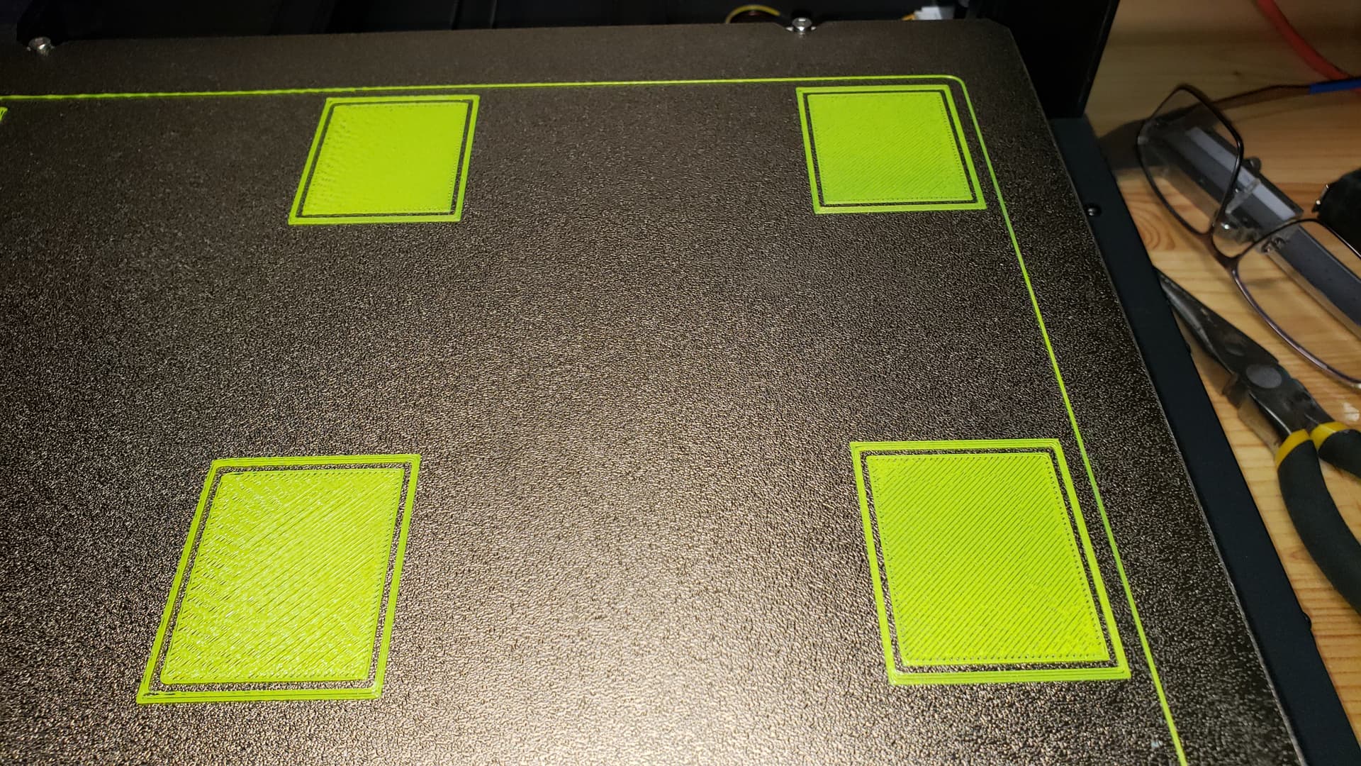
In the shots below, you can see the left side adhesion isn’t fantastic, and the filament is not getting side to side bonding - not enough squish. Everything looks better on the right side - Not solid films of plastic… but definitely better than the left side. I took one overhead shot, and four shots to show the quadrants, unfortunately, those are a bit angled. The one shot where the skirt on the object is bent? that’s due to the nozzle catching it as it moved to print the middle square - clearly we’re close to the bed, just not close enough?
PEI sheet has Elmer’s glue stick, thinly applied, and carefully turned into a fine film using a dampened shop towel, then dried in place with the heated bed on.
Firmware on the printer is 1.0.12, Screen fw. is U121. H/W version is CR-FDW-v2.5.S1_100.
Thoughts on what else to do, other than buying a set of these https://www.amazon.com/dp/B09NQG6SMH?pd_rd_i=B09NQG6SMH&pf_rd_p=05cb97ea-f4ff-45cd-bc16-8d8137cb8201&pf_rd_r=2SFNXRSJMTTNKK9ZKDJR&pd_rd_wg=HtxMq&pd_rd_w=gFvvY&pd_rd_r=26e6d59e-d9e0-42cf-812c-81f707771721 ??
Given there are two motors, is there a chance that one’s just not turning as fast as the other? if so, why isn’t the set of couplers and belt at the top not helping compensate? (they don’t both have diff. e-step values do they? If so, which magic door gets me to them to check and adjust).
Pic 1 - whole bed

Pic 2 - Rear left quad

Pic 3 Front left quad

Pic 4 Front right quad
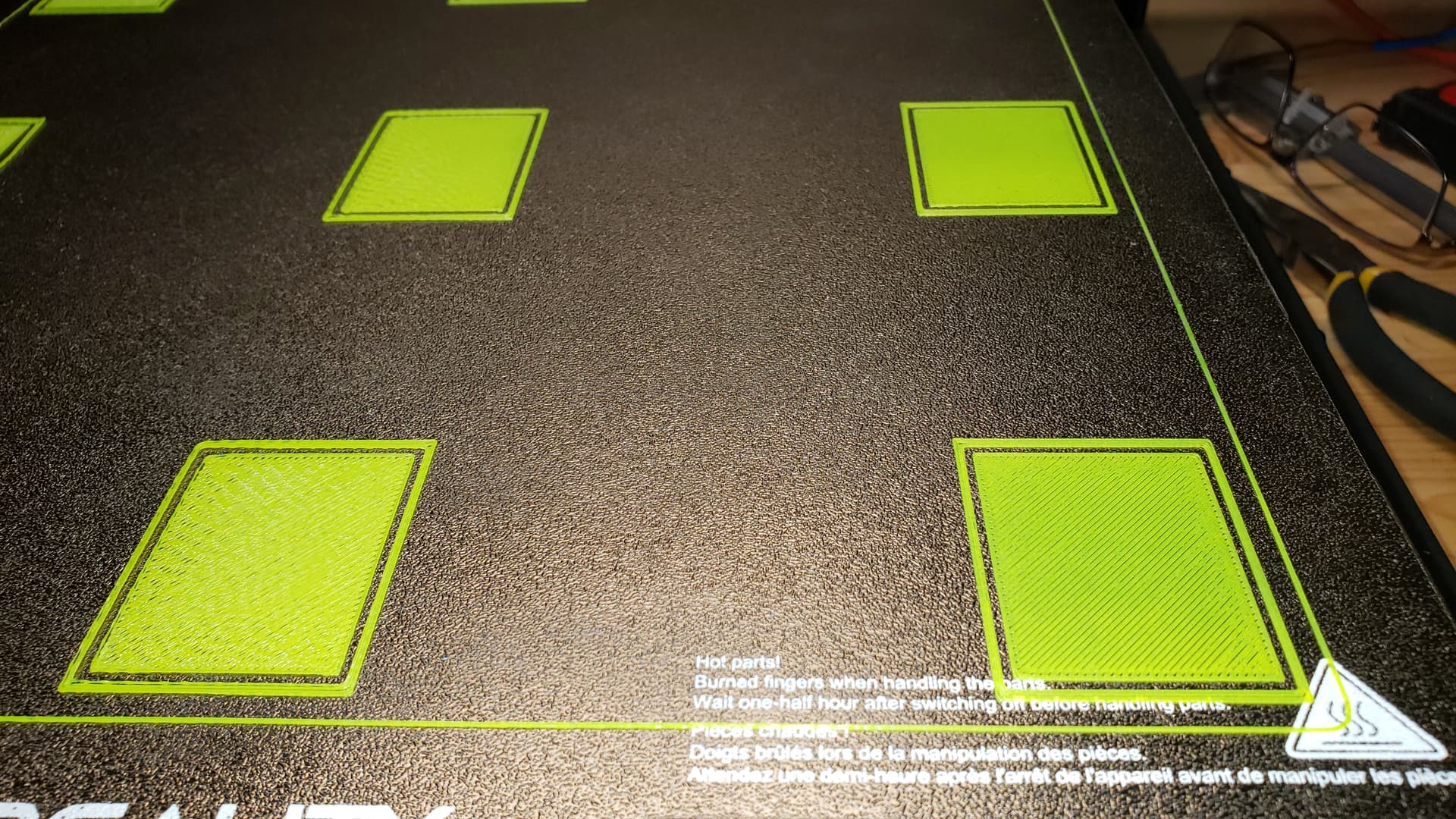
Pic 5 Rear right quad