Hello guys,
I’m printing with a CR 10 S Pro v2 and I ran into a slight problem, involving lining up the length-axis of my object.
If I line it up along the X-axis, the print devellops deviations of the printed layers. In general the printer follows the form of the object, but the resulting surfaces are very rough. When I line up the same object along the Y-axis, the surfaces are clean and smooth.
As I’m using a black fillament, photo’s will not show the problem clearly, so I didn’t include any.
Does anyone know, what’s happening?
Regards Richard
is it across the entire Hight of the item you are printing or just towards the bottom?
Hi Jason.
It’s across the entire hight. But note everywhere evenly distributed.
Pictures can still be helpful, even if the filament doesn’t have a high contrast.
I’m trying to visualise what you’re talking about.
Is this what you mean by “length-axis of my object”…“lined up along the X-axis”? (X-axis is red, Y axis is green)
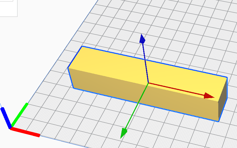
And similarly, is this what you mean by lining the length-axis along the Y-axis?

The Z-Axis is the vertical axis (blue in these pictures).
I’m confused because this sort of question usually gets asked about why standing an object on it’s end produces different results vs. laying it flat. Both the above examples have the object “laying flat”.
The stepper motors for the X, Y and Z axes are typically the same model and typically make 200 full steps per revolution.
The X and Y axes are moved by belts that run over pulleys so how far the print head actually moves is a function of the pulley diameter. On my Ender 5Pro, that one full rotation will move the print head 40mm.
By comparison, the Z axis is driven by a threaded rod so the amount of movement is determined by the pitch of the thread. On my 5Pro, that means that for one full turn of the stepper, the print head moves only 2mm.
Hence you can get 8X finer (smoother) resolution on vertical surfaces than you can on horizontal surfaces. That’s the kind of question/answer I was expecting, but the phrasing of your question suggests you are getting different results by turning the model horizontally? Am I understanding you correctly?
If this is actually the case, there is a setting that determines how much each axis rotates per mm of movement. They should be the same for X and Y but for some reason, yours may not be? Again, that’s if I’m interpreting the question correctly.


So, the surfaces that are facing the camera - where they the surfaces that were on the bed? If not, then which surface was in contact with the bed? It looks like the top print was printed with the bed either at the top or bottom of the photo, either of which would imply the print was balanced on a point, presumably with a support.
Sorry if I’m a bit thick, but I’m really having a problem visualising the orientation of this piece on the printer.
Can you point me to the STL for this object?

Ah. OK… That helps enormously.
Have you checked that the belts are tight? There should be no movement in carriage when the motors are enabled. the top photo looks to me like there’s some play in the carriage such that it’s not stopping exactly at the edge of the model, but overhanging slightly.
I have to step out for about 2 hours but I’ll be back.
Thanks.
I’ll check the belts.
Both belts are nice and tight.
As it is now 23.20 hrs here (The Netherlands), I’ll be in bed when you return.
So I’ll speak to you again tomorrow. 
Can anyone else chime in here? I thought for sure that since this was an X-axis specific defect, that it would indicate a loose belt. I’m struggling to think of what else could create a problem on only one axis.
Given that it’s a CR10, are the wheels under the bed properly tightened? They should be able to be turned by hand with some effort, but I suppose if they were really loose, they could cause the bed to wobble in the X-axis direction?.?.?
Is there any wobble in the gantry? Although I would expect that to show up in both X and Y directions, but I suppose it could be tight along the Y-Axis but have play in the X? I’m starting to guess here.
Can’t help I don’t see how the orientation works is it possible the Z axis has bent rods and the X carriage is moved slightly left and right as the print progresses?
I would argue ‘no’. If the problem is with the Z rods we would be seeing an overhang every time the rod made a full rotation. If the Z-rod’s threads have the same pitch as on my E5Pro, that would mean an overhang every 2mm vertically. The problem looks semi-random, which I think/thought would be consistent with a loose part (belt/guide wheel/ bolt holding the X-axis to the guide wheel).
In my (limited) experience, in the category of axis-specific problems; cyclic flaws are always caused by rotating objects (dirty guide wheels, bent shafts), seemingly random but consistently located flaws are caused by debris (dirty guide rails, debris in a belt), large, random flaws (layer shifts, for example) are generally caused by external interference (cable snags, animals whacking the printer, etc.) and small, seemingly random flaws are almost always loose components. Despite Caistor’s assurance to the contrary, I’m hard pressed to think of anything else that could cause this.
I am seeing a lot of ringing in both. I agree something is loose and just more prevalent in one axis. The gantry could also be slightly out of true.
Ok guys. Thank you for your input.
Tomorrow I’ll give the machine a thorough inspection.
I’ll let you know the outcome.
Right now, the printer is busy printing the complete part, of which take-one and -two is the front part.
it almost looks to me like the nozzle has gone bad. maybe become deformed ?
If its consistantly in the same direction but inconsistant on extrustion I would look at it.
If you change nothing else except orientation of the model and the defect is always on the same side?
I guess a kind of conformation of this is to check that both sides are defective the same amount/location?
I know that sounds like an odd question but if the defect overhangs on the left and indents on the right that would sound like loose bearing, if it indents on both sides on the same layer that tells me nozzle.
Belts may be tight but is the idler pulley snug to the motor spindle, had that happen once.
Good point. I should have thought of that. @Caistor check that the set screw holding the pulley to the stepper motor shaft is tight. If it’s allowing for some wiggle, you’ll get the results you’re seeing. Thanks @3DMultiMaker
Hmmm I would agree with Jason it could also be the nozzle they don’t last long and the market is flooded with really poor quality ones that are bad from the start. It is an easy replacement.
An axis-specific nozzle problem? I suppose if the nozzle wore out on one side rather than more-or-less evenly, it could happen.