I altered the pegs by stacking them to print in a single piece…
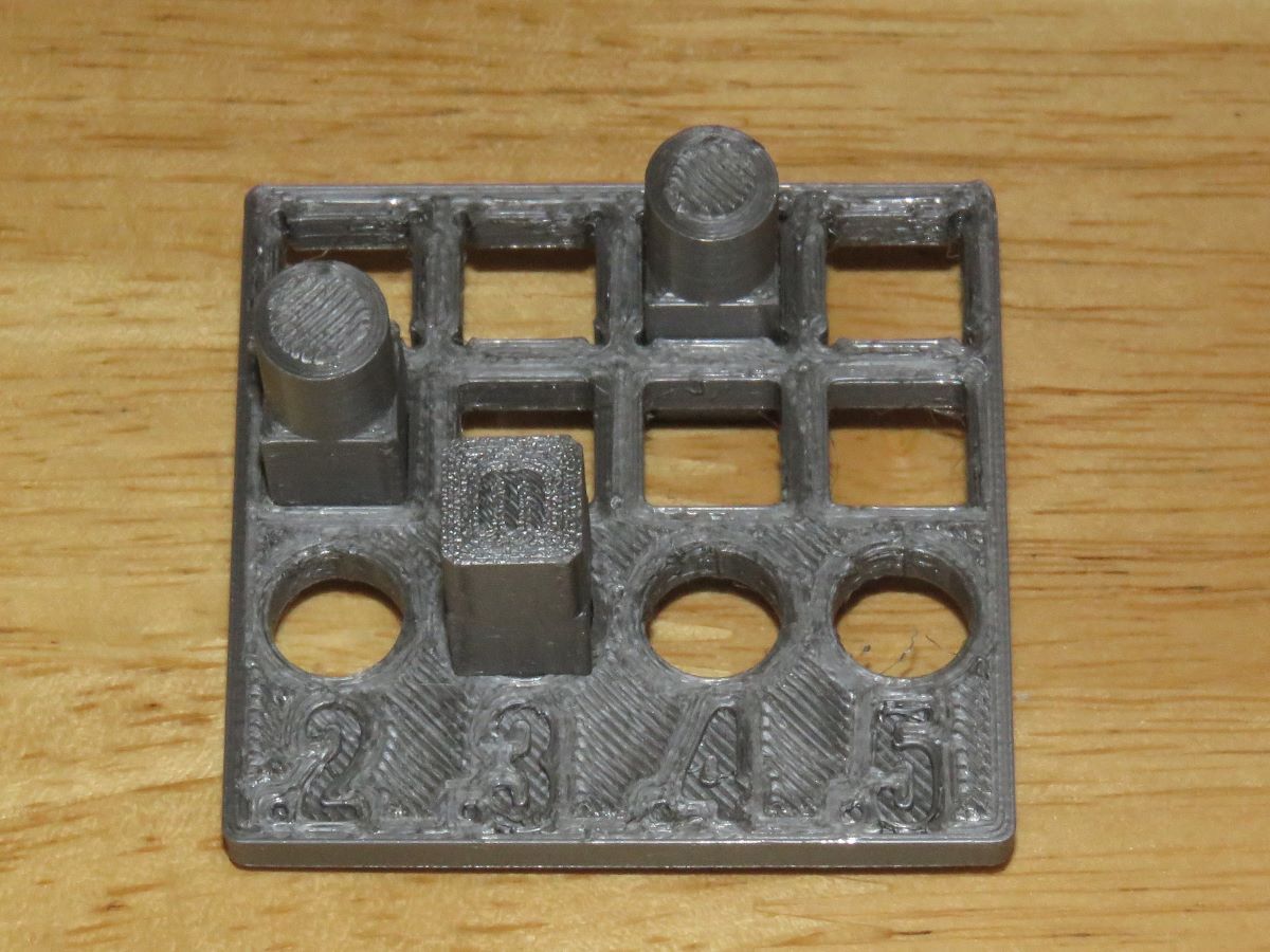
The peg has three parts, all printed to a (theoretical) size of 10mm… round (left), square (center), and square with beveled corners (right)… I printed three, using the CURA “Slicing Tolerance” settings (found under “Experimental”) of “Inclusive”, “Middle” and “Exclusive”, and since these shapes are not tapered, that made no difference in the size… I actually printed two plates as well, using "Middle’ and “Exclusive”, and that made no difference in the size either… Here are the pegs sitting in the holes that gave the best fit… The numbers are the amount the holes in that column are oversize (larger than 10mm)…
By “best fit”, I mean large enough to slide in easily, but not so large that the peg will fall out (which they will do in the next largest hole)… You can probably force the peg into the next smaller size hole… I did file off the “Z” seam on the pegs before trying them… The top row of holes in the plate are relieved at the corners of the squares, because printed squares tend to have a “bump” on one side of the corner… The second row are simple square holes, and the square peg with the beveled corners is the test piece for those…
I was using PETG in my Ender 5 S-1, and of course other materials may yield different results… but these are good starting points for a good fit with the shapes tested…
Nice! I use a different test but if you are printing functional tests it is very important to know the finished sizes.
I personally like the Clearance/ tolerance test from Angus (makersmuse) but of late I am using the clearance castle tower only or if I have lots of time the whole castle. It is a good indication of multiple things.
If you are running tolerance tests I think running at the speeds you usually print. I tend to print quite fast and a test at speed is not always the same as one slower.
Yes, I have found that printing speed makes quite a difference on sharp corners, such as on a cube… If you print very slow, there is hardly any “bump” on the trailing side of corners, but if you print at normal speeds, there is a significant bump when the nozzle makes a 90 deg. turn at the corner… I guess momentum is carrying the print head past the corner, so you get a bump as it is making the 90 deg. turn… That is why the pegs with the beveled corners fits in a square hole, but the square peg needs a square hole with clearance holes in the corners, so that the bumps can slide into them!.. You get a smaller bump on the outside corners of a hex, even smaller on an octagon, and of course none on a cylinder…
When I need a clearance for mating parts I use the following rule that works well for me.
Loose fit 0.4 mm clearance and tight fit 0.2 mm clearance between parts. The tight fit does make it harder to take apart so that is why I use the 2 different settings. I typically only use PLA. Those clearances may be different for other materials.
I have never tried a tolerance test buy I should just for shits and giggles.