Heating failed. Bed PRINTER HALTED Please Reset

I have a 6yr old CR10 S4 (400mm X 400mm). It has 2 slides for the ‘Y’ axis bed and 2 ‘Z’ screws. At that time I was offered the printer with a ‘touchscreen’ so I opted for that. The original MB was a Creality MKS Base V1.5.The printer has operated flawlessly since day one.

I recently decided to upgrade the printer and installed an SKR 1.4 Turbo, TMC2209 drivers and TFT35. Please note I’m a newbie with all this stuff and completely new to Marlin.

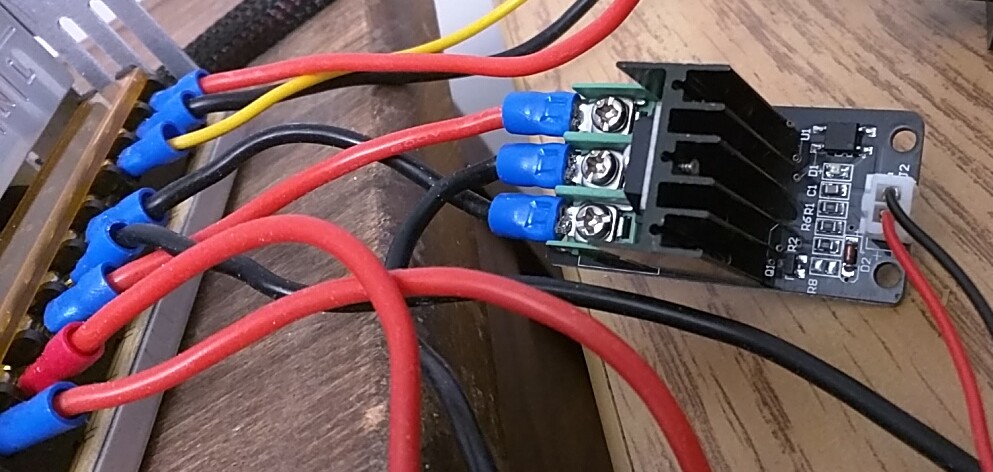
I understand basic electronics with respect to polarities, etc, but I’m not so familiar with components. Here’s my current problem. Tested nozzle heating, OK. Tested bed heating, temp increased from 22c to 29c…failed. Photo attached of current connections.

Message: “Heating failed. Bed PRINTER HALTED Please Reset”.

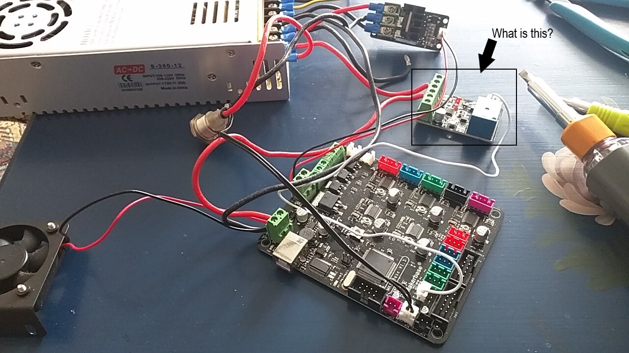
Checked all wiring okay. Tested some leads for continuity, ok. Nothing had ‘smoked’. I noted that there was another component which looks like a mosfet (see photo) but I think it is some kind of relay and is the cause of my problem since *I did not install it. There was a little wire (white) connecting that component (relay) to the D12 plug of the MKS motherboard. D12 seems to be used for a ‘servo’?? What would they have connected that to? Anyway, the guys at 3D Printing told me it wasn’t needed!? I have a feeling that it is and now I don’t know where to connect that white wire on the SKR board.

Any help would be appreciated cause I’m at my wits end trying to find an answer to my problem on the web.!
Current connections|690x388 !
What is this|690x388

1 Like

First off, I’m not familiar with the CR10 so if some of my questions seem odd, it’s because I’m comparing it to my E5Pro.

Is the thermistor for the bed properly attached to the bed itself? For that matter is the bed heater properly attached?

You’ll get a ‘heating failed’ error if the thermistor or heater become disconnected - that’s the obvious one, but you’ll also get it if they aren’t making good contact with the bed. The controller applies heat and expects the bed temperature to rise at some minimum rate. If either or both of the heating element and the termistor are not in good, solid contact with the bed, the rate of heat transfer will be slower than the controller expects, creating an error.

Some clearer pictures of both the MOSFET module and the relay module would be helpful. I couldn’t find either of them with a Google image search to confirm that they are, in fact, a MOSFET and a relay board.

I find it odd that they’re using an external MOSFET board when there’s a MOSFET on the motherboard already. Has the printer been modified to use the more powerful heater, something beyond what the motherboard’s MOSFET is rated for?

As for the relay board, that’s odd for two reasons: 1) relay outputs are generally isolated from the control signal, so you would need at least 4 wires in order for it to actually do anything and 2) there are an awful lot of components on that board for a simple relay. See the photo below for comparison and why I’m wondering if there’s more to it.

Okay, I’ll try to provide you with satisfactory answers.
The thermistor is very well attached and has never been touched till now, to look at it.
I checked the bed temp settings in Marlin (adv.h) seems ok.
When I started the bed heating process the temperature DID change from 22c to 29c before generating an error message. So it looks like the thermistor does get a reading and I can feel a subtle change in temp from my hand placed on the bed.
The mosfet and relay were already installed in the control box with the original MKS motherboard. I did not install these but figured they must be needed. That’s when I contacted 3D Printing CA and they told me the relay wasn’t necessary. They didn’t say not to use the mosfet and I didn’t ask. I bought the SKR 1.4 Turbo from them and they didn’t say, “OH don’t use a mosfet with that board because it has one built in”! So…now I don’t know if I should be using it or not…maybe that’s causing my issue. I simply don’t know what to do now. Pictures of mosfet and picture of relay below.

EDIT: Before you read the rest of this, can you confirm that the bed is the original unit?
Can you also confirm that the bed is using the original heater?

I ask this because, in doing research on this, I found that some users are using 120V bed heaters to bring the bed up to temperature quickly. In order to control the 120V bed heater, they are using an EXTERNAL MOSFET module like you have on your system.


From what I’ve been able to research, the CR10 S4 uses a 220W bed, so at 24V it will draw about 9.1A.

I could not find anything about what the output wattage for the bed is on the SKR 1.4 Turbo or what it was using for an output MOSFET.

I have an SKR Mini E3 V2.0 which uses a WSK220N04 which is rated at 220A continuous (!?) and, looking at the photos of the SKR 1.4 and based solely on it’s size and packaging type, I’m guessing it’s a similar, if not the same, MOSFET.

So, based on that, I would take the MOSFET module out of the equation. If the bed is the original CR10 S4 bed and it runs at 24V (it should say so at the power terminals on the bottom of the bed), then you should be able to run it directly off the SRK 1.4 Turbo.

Similarly, that relay board is one wire short of being able to do anything, so take it out too. I supposed it might have been used to run some lights? I can’t think of what else one would do with it. Either way, the input needs at least a ground lead. By the way, does the relay module have anything written on the bottom? It’s a bit of an odd duck given that it appears to have both an opt-isolator and a relay, both of which perform basically the same function (signal isolation).

As for the firmware update issue, different printers come with different thermistor models. You MUST specify the correct thermistor in the Marlin config files so that the software knows how much of a change (and in which direction) it should be seeing in the termistor value as the heat is applied. If the change in temperature does not match what it’s expecting, then it triggers an error.

Finding what model thermistor the CR-10 S4 uses for the bed is like pulling teeth. The only reference I could find after more than 2 hours of research is that it is probably an ATC Semitec 104GT-2.

Creality has a video about changing the bed thermistor but never actually tells you what model thermistor you replace it with. Pleas for that information in the comment section go unanswered. Why is this a State Secret?

Worse, comes to worse, comment and un-comment different thermistor models and find one that works.

Legomaniac, yes, my CR10 is ALL original except for the MB (now SKR 1.4 turbo, 2209 drivers) and TFT35. The bed and heating element are original. The heating element rated at 12volts, how many watts I have no idea. My original power supply Output is 12 volts/30Amps NOT 24volts.
The SKR 1.4T is rated at 12 or 24volts so I figured it must be okay for my 12 volt system. I also figured the PSU to be sufficient since it worked fine before. The bed used to take about 6minutes to get to 55c. Yes, I’ve seen very special Mosfets being used to power the bed element when people use a separate PSU to power the bed so it would heat-up and maintain a higher temp, so WHY Creality installed a separate Mosfet along with a separate relay on my previous set-up I have no idea, unless their MKS MB didn’t have an integrated mosfet??
Yeah, I had tried to find which thermistors Creality uses but no luck so in Marlin ‘Config.H’ I selected Number 1 for both the bed and nozzle as suggested by Marlin when thermistors are unknown (see below).

#define TEMP_SENSOR_0 1 (change to 5?)
#define TEMP_SENSOR_1 0
#define TEMP_SENSOR_2 0
#define TEMP_SENSOR_3 0
#define TEMP_SENSOR_4 0
#define TEMP_SENSOR_5 0
#define TEMP_SENSOR_6 0
#define TEMP_SENSOR_7 0
#define TEMP_SENSOR_BED 1 (change to 5?)
#define TEMP_SENSOR_PROBE 0
#define TEMP_SENSOR_CHAMBER 0

Your suggested thermistor would have me change my thermistor selection from a number 1 to a number 5 ( 5 : 100K thermistor - ATC Semitec 104GT-2/104NT-4-R025H42G (Used in ParCan, J-Head, and E3D) (4.7k pullup)). Should I change to number 5 for both the bed and the nozzle?
I visually inspected and checked the bed wires for continuity and all seems fine. The single wire on that relay module used to be plugged into the D12 (servo?) of the MKS board, what it did I don’t know. My CR10 never had LEDs but did have a filament runout sensor which I never used nor connected. My guess is that relay handled something with lots of power because of the gauge of the wires. There’s nothing written on the bottom except to identify the 6 connections being: a + (pos) and a 24v /2-‘OUT’ /2-‘Button’ and a Creality stamp. I’m willing to eliminate the Mosfet which I guess means I would simply connect the red (Pos) and black (Neg) wires directly to the PSU? I assume the thermistor controls when to turn the bed heating element On/Off like the thermostat does when heating our homes? Boy…if that works I’ll be blown away. I’d rather eliminate the mosfet altogether.

I’ll wait for you to confirm connections without the Mosfet, if that doesn’t work I’ll play around with some thermistor settings. I’m researching as much as I can including watching about 200hrs of YT but am running out of options. I also saw that Creality video on the thermistor replacement, and you are correct, they don’t tell us a darn thing about the thermistor both in the vid and description.
Hey, I really appreciate your help.
I can see you’ve spent a lot of time researching stuff for me and I find that to be so kind during these trying times when people aren’t respecting one another so thank you so much!! You have no idea how much I value your feedback, at least someone is trying to help me.

OK, so, the CR10 S4 is a 12V system with a 12V heater on the bed and a 12V power supply. I hadn’t realised that. My Ender 5Pro is all 24V. It’s just as well. The greater risk is attaching a 12V component to a 24V system, but given that it’s a 12V system we should be able to proceed without risk.

By the way, did you get the printer directly from Creality? I just can’t understand why there was a MOSFET module and a relay module. MOSFETS are usually used to control high-voltage or high-current devices from low-voltage, low current controllers, yet your controller operates at the same voltage as the bed and the on-board MOSFET can handle the current. Relay boards (as far as I’ve seen) are generally used for lighting systems because the controller boards can’t put out enough current for an LED strip, yet that doesn’t appear to be needed either. Very strange.

Are you able to read the part number of the MOSFET on the controller board (for the bed heater)? Is it the same WSK220N04 as is on mine?
I’m still puzzling as I write this about why they had an external MOSFET installed… If it’s not to adapt to a higher voltage, is it to supply more current than the motherboard can handle? Still, MOSFETs are beasts, but a 220W bed on a 12V system should draw about 18A which should be well within the range of the MOSFET.

------ Hours later after a nap -----

While doing more research, I stumbled up this:

It’s the usual Creality video: long on video, short on specifics and I learned 2 things from it:

  1. your printer comes with a sprinkler head
  2. the MOSFET module is part of the original machine and is used to control current to the bed.

One of the main reasons more recent 3D printers are using 24V power systems is that you can deliver the same amount of power (W) with half the current. Doubling the current on a 12V system means the PCB traces have to be twice as wide which takes up more board space.

So, proceed to wire it as they show in the video

I suspect the “Heating failed” error is due to the default firmware expecting a different thermistor than is installed in your printer. I’d suggest trying different thermistor setting in Marlin to see what works.
At best, it will work reliably. Second best, you’ll get another “heating failed” error. Worst case, the board temperature will skyrocket and you’ll have to turn the machine off. (but I doubt that since we know the thermal protection system works).

I actually started this post yesterday, shortly after you posted the reply above, but I haven’t slept well in days so it’s been difficult to be coherent. Hopefully I’ll get a decent sleep tonight, and if you try following the assembly video, I’ll try and be more coherent tomorrow. Obviously, you will need to substitute the connectors on the new controller board for the corresponding ones on the old board shown in the video. If you still have problems with your sprinkler system, post details here and we’ll continue moving forward.

Hi LEGOManiac, hope you had a good sleep. First, I’ll try to answer your questions and provide more info.

  • I bought my machine 6yrs ago from ‘The Creality Store’ via AliExpress. Like I said, since they offered me a touchscreen option, no printers had those at that time. When I got the printer the control box looked like it was made from a ‘project’ box because it was rectangular with visible screws, open gaps around the touchscreen, I wasn’t impressed but it worked flawlessly! After I bought it they no longer offered the touchscreen because I checked and sent other YouTubers to the site, no longer available at that time?
  • No P/N’s are visible on the Mosfet nor on the board it is soldered to. I checked the specs of the original MB and couldn’t find anything about output to the bed, so they must have put an external mosfet to ensure good current to the bed? Just guessing here.
  • I found this statement on the last page of the BTT SKRV1.4 Turbo manual, this is what it states:
    “The power of the hotbed connected to the motherboard must be less than or equal to 144W (that is, the thermal bed resistance is greater than 1.0ohm). If you want to use a high power hot bed, you must connect an external hot-bed power expansion board”.
    FYI…the resistance on my hot bed is 1.4ohm.
    From what I can see from a calculator on the web, 144w = 15amps at 12volts, so my new SKRV1.4T will need an external mosfet…would you agree? Won’t my 400mm X 400mm bed size demand more amps? There’s nothing on the web providing specs for this size of bed.
  • I found a method to test the mosfet on the web and from what I see, my mosfet is defective. I don’t know if the fact that the mosfet is soldered to a small PCB affects this test?
  • I had to laugh at the Creality video link you provided because I had already seen it, great minds think alike, ha,ha.
    Yes, my wiring is exactly as in this video and had been recommended by the guys at 3D Printing Ca. It’s been that way from the beginning and still is.
  • I just ordered a new (3 screw) mosfet to install and a (spare) thermistor (in case). BTW, from what is see, mosfets with 3 screws only power the bed OR the nozzle, mosfets with 4 screws power both the bed and nozzle. From what I see the thermistors should be set to number 1 in Marlin or number 5. Delivery of my order is expected at the end of May beginning of June…geez ay!
  • I’ll test the new mosfet when received to see of it acts the same as my original one, hopefully, it will as test it should and if it does, then, my problem was with the mosfet, if not I don’t know what to do except to reassemble my control box with the original parts and just forget about upgrading the printer.
  • You say that I have a ‘sprinkler’ system on my printer? I’m NOT aware of that and have no idea what you are talking about? Please excuse my ignorance as I’ve never heard of a “sprinkler” on a 3D printer so that’s new to me.
    Again, thank you so much for your help and patience but I don’t want you losing sleep over it. Hopefully we’ll find an answer and both learn from this.
    Stay safe!

Lol … I had to read the text in the video he posted to figure this out too. They translate hot end as sprinkler in the captions

One thing about the hotbed draw if you heat the hotbed all the way before you heat the nozzle you can avoid some load on the board. Once the bed is hot then the heater will draw a lot less current than when it’s cold.

Glenn, thanks for pointing that out, I hadn’t caught that.
Good point about bed heating, which I’ve always practiced.
It’s amazing how these, what we think will be ‘simple mods’, turn into nightmares.

Sprinkler Head, is what Creality called the Hotend assembly.

It’s a “Lost in Translation” from the Word Extruder ~ Sprinkler

The Black 3 Wire MOSFET is a Bed MOSFET.(They’re green PCB in current models)

  1. Positive from PSU
  2. Negative to BED
  3. Negative From PSU

The Black 6 Wire MOSFET was used as a remote power on function Switch
It would power on the Control Board using the Servo Pin as a signal sensor

Can you explain this in more detail? I couldn’t figure that module out last week.

There’s a black 5-wire MOSFET module. 2-wires for control signal, 3-wires for switched ouput) that I initially thought seemed pointless until I realised it was a 12V system and the current drain was probably more the the controller PCB could handle, so it was just being used as a high-side switch for the heated bed power.

Then there’s the BLUE, 6-wire, relay board, which had 1 wire going to the original controller board’s D12 I/O pin. It seemed awfully complicated for a simple relay board. Is this the second board you’re referring to as a MOSFET? Anyway, both you and @Rotorfreak have been referring to this having something to do with “servo”. There are no servo motors on a 3D printer. What would they be used for? As initially wired that board didn’t have a return ground path for the D12 signal. You say it’s used as a “power on function switch”, but you say it would be powering on the control board? If the control board was off, it wouldn’t be able to detect a signal on D12 (if D12 is programmed as an input), but if D12 is programmed as an output, what would it be controlling? My guess was a light strip, but otherwise I really can’t see any point in it.

I have a feeling, and this is a guess, that Creality (or whoever assembled the unit) installed that separate relay to work with the filament runout sensor (microswitch) which as I mentioned never used. I the filament breaks don’t you want to stop heating the nozzle or bed? I have no idea what triggered that D12 pin. Anyway, my project is completely ‘on hold’ waiting for a new mosfet from China via Amazon. How discouraging because if I connect the new mosfet and end up with the same problem I’m screwed.

YIPEE…MY BED IS HEATING!!! Don’t worry I’ll explain what I did, hopefully this experience will help others following this issue. I received 2 mosfets today, one with 3 screws and one with 4 screws. Decided to use the latter. Here’s a link to that one https://www.amazon.ca/gp/product/B07K445TDQ/ref=ppx_yo_dt_b_asin_title_o00_s00?ie=UTF8&psc=1 .
I connected the 4 screw mosfet, turned on the printer setting the bed temp tp 50c. At 29c it failed?? Same message as before, “Heating Failed: Bed, PRINTER HALTED, Please Reset”. So I changed the setting in Marlin Config.Adv.H line 223 “Watch Bed Temp Period 60” and line 224 “Watch Bed Temp Increase 6”. I changed Temp Period to 40 and Bed Temp to 2. Uploaded the .bin file tried heating the bed to 50c and it worked!!! It took about 8 minutes to get to temperature which is acceptable for me. I checked the bed temperature and it remained within 1 degree…pretty darn good. The mosfet turns on and off as it should. I’m thrilled.
Here’s a few of my observations going through this process:

  • Appreciate everyone’s feedback, you never know what someone may say which can ‘turn that light bulb on’ thus contributing to a solution, so thanks everybody for your comments.
  • Learn as much as you can about Marlin and your printer.
  • Learn about how the power is furnished and updating firmware.
  • What may seem obvious sometimes isn’t and unfortunately you may have to watch many YT vids including older videos in order to figure things out. Thank goodness for Forums!
    I still have many questions but will post those separately on this forum.
    So to make a long story short, the issues I experienced were ALL related to settings in Marlin and nothing to do with hardware. My next project is to install the BLTouch and after that a Micro Swiss Direct Drive Extruder. Take care everyone and stay safe!! Again, thank you all for your help.
1 Like

I’m puzzled then, about why this became an issue? Did the printer get moved to a much colder environment? Your Marlin settings only changed how long the printer waited and what minimum temperature change over that time, before it considered it a failure. The only time I’ve ever seen this happen before was when people moved their printers into the garage in winter where the cold air against the bed meant it exceeded the time limit and undershot the minimum temperature increase.

Anyway, I’m glad to see you got it going and, yes, I’ve learned something from your experience.

Actually, the printer is in the exact spot since day one. My problem all started because I’m new to this stuff. Having to learn Marlin and what all the settings did was daunting. Then having to learn about printer components and how the whole system worked was another thing. On top of that connecting a new MB and setting up Marlin I was bound to run into problems which I expected. be reminded, I had problems with updating the MB firmware!! I just didn’t think finding answers would be so hard. There were some settings in Marlin which weren’t correct from the start that I had to figure out. Finally, after grasping the silliness of firmware update failures or why extruder head movements were incorrect and why my bedsize was incorrect even though in Marlin they were good? I finally arrived to the heating problem. This was very frustrating. Finally, in the end I timed the heating and checked temps which pointed me to check the settings in Marlin. Changing the bed temp check from 6 to 2 did the trick. Now I’ll finish printer calibration and complete my other mods. Onward and forward…hopefully!