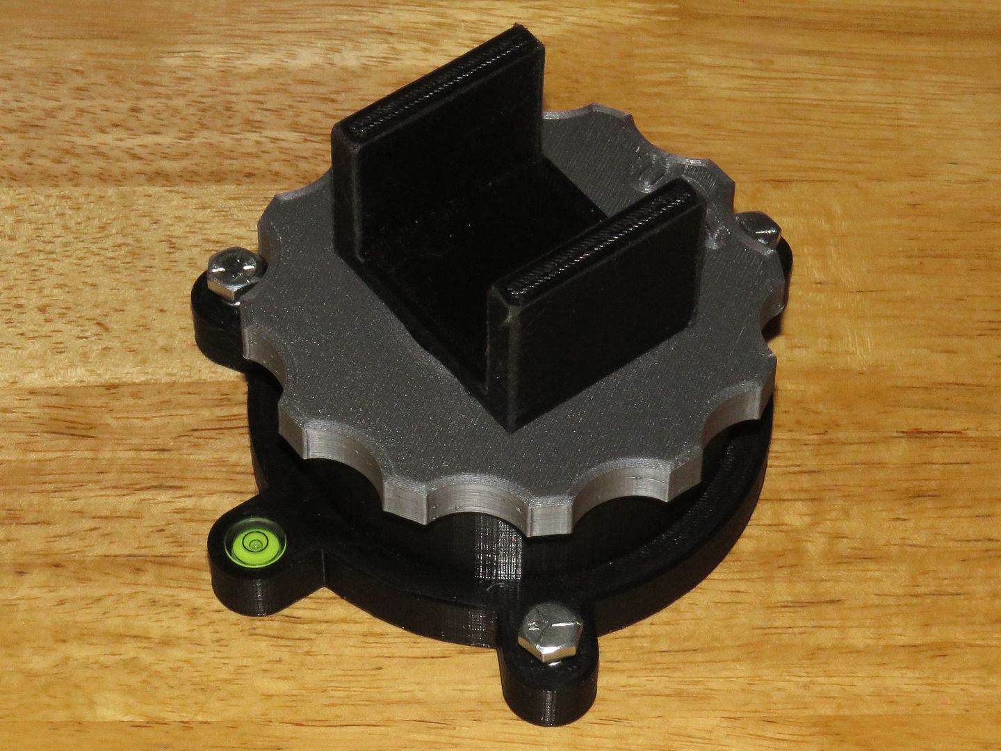
I recently saw something similar, and redesigned it for home 3D printing, and improved it… On the original you had to hold the base from turning when adjusting the height, on mine I used a keyway to allow the stock cradle to adjust for height but prevent the base from turning with the stock in the cradle… I want to be able to primarily use it for my new Dual Tank PCP Benchrest rifle, where the buttstock will be a straight piece of 2x4, with the bottom parallel with the bench, so the cradle is 40mm wide and flat in the bottom… However, I also have V-block inserts to fit stocks with a rounded toe, and different heights of inserts to choose from as the vertical adjustment is only 10-15 mm (there are 20mm of threads)… Here is what it looks like…
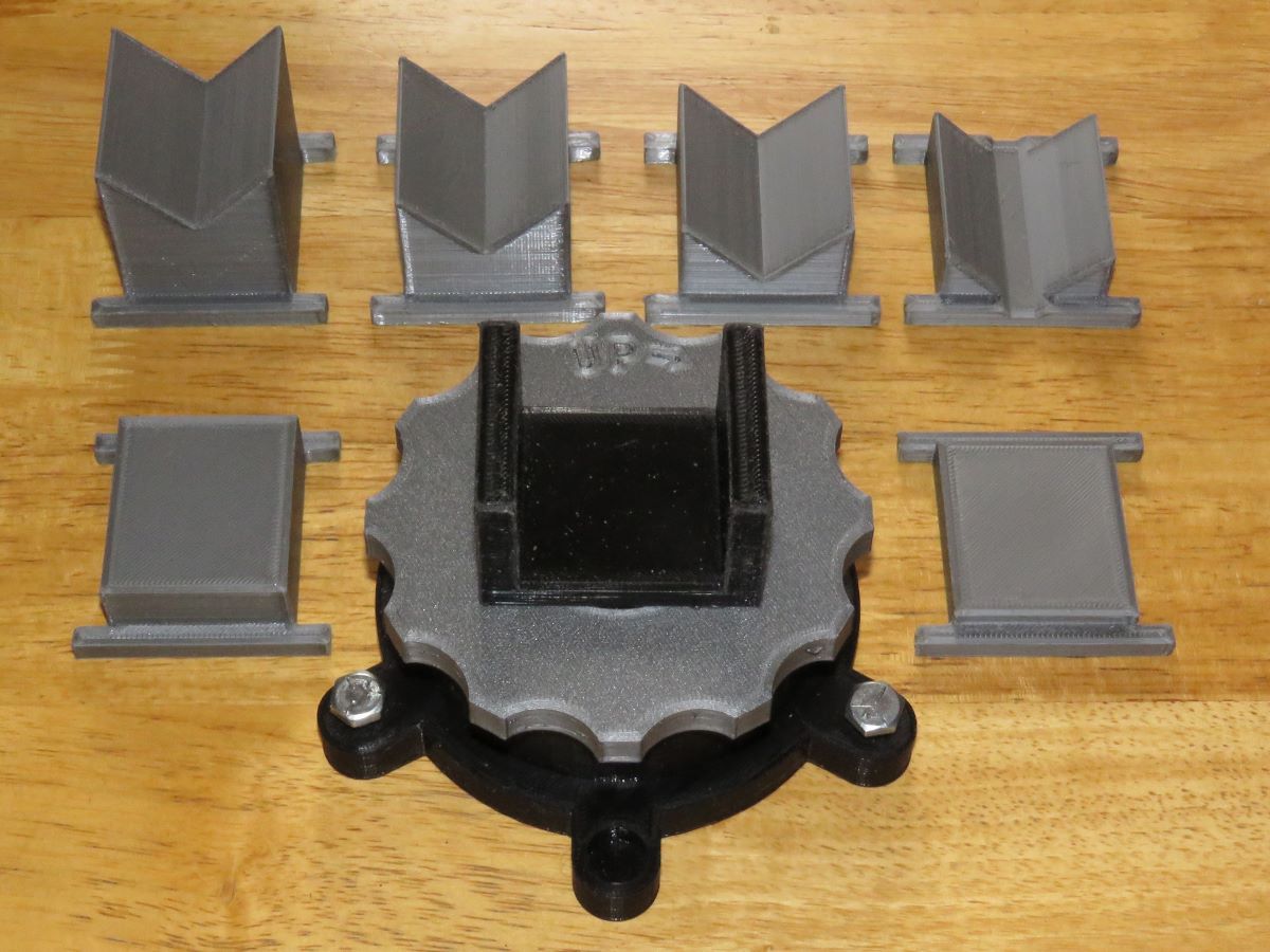
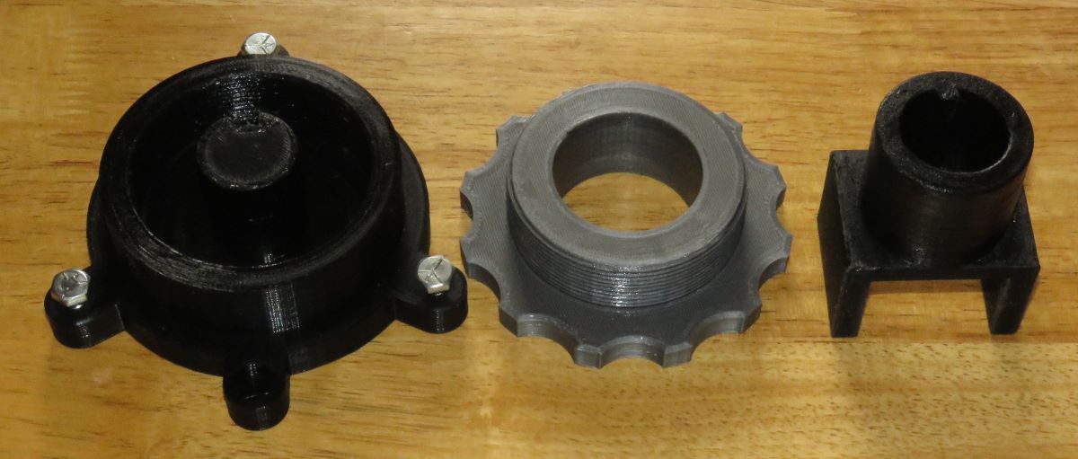
Here are the main parts disassembled… The thread is 75mm x 2mm pitch… You can see the keyed cradle support, and the keyway in the post in the middle of the base… The fits are good, and basically there is no significant side play in the assembly… There is a small hole for a round bubble level, and three adjusting screws to level it before use… The threaded holes for the 1/4"-20 NC 1" long bolts need chasing with a tap… If you tap from the top, and don’t quite go through, the bolts will be tight enough to not self-adjust…
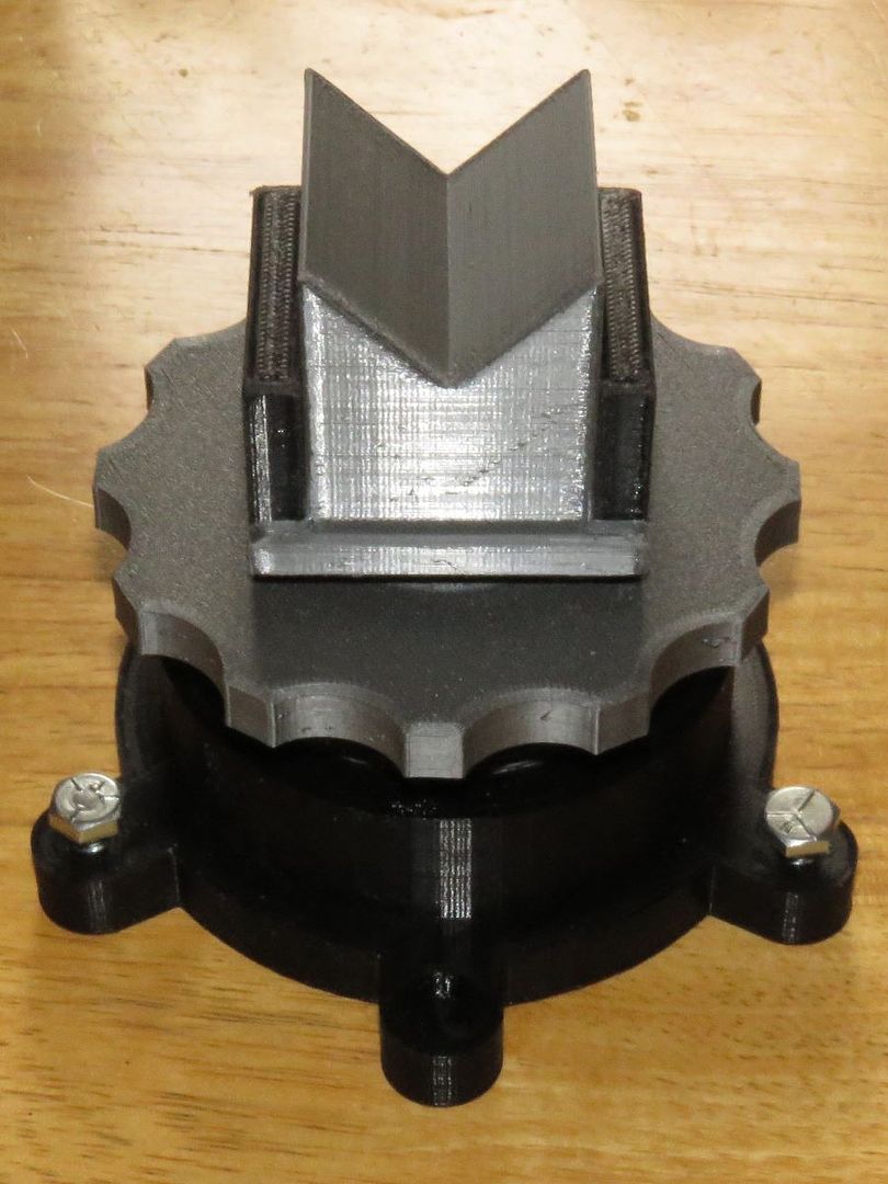
Here is the tallest insert in place, and the adjuster cranked up to maximum height… At it’s lowest, the bottom of the stock is 2" above the bench, with over 1/2" adjustment up from there… The inserts each add 10mm, and you can make them any height and shape you want… they just drop into the cradle…
I used PETG, nozzle at 250C and the PEI build plate was at 80C… I printed on an Ender 5 - S1 with a 0.4mm nozzle, using the Cura slicer, at “100 mm/sec”, but set the infill speed to 80, and the walls were done at 50… I used “Adaptive Layers” to make the threads from more layers (using 0.2mm layer height, with 0.08mm variance, so the layers for the threads were printed at 0.12mm thick… I used a 40% Cubic Infill, 4 walls and 8 top and bottom layers, and it took 14 hrs. to print the base, about 7 hrs. for the screw adjuster, 4 hrs. for the cradle, and a couple hrs. each for the inserts… Supports are needed on the Cradle, but not anything else (the screw adjuster is printed upside down)… You can reduce the number of walls, top and bottom layers, and infill density on the inserts, they don’t need as much strength…
I undersized the diameter of the male threads by 0.8mm, and the height of the male thread profiles was scaled down by 5%, both of these to allow clearance… After careful deburring and cleaning of the male and female threads, and a slight sanding of the OD of the male threads to get rid of the pointed crests, the thread are a great fit… I used SuperLube Silicone/PTFE grease on the threads and sliding post with key, and the OD of the cradle where it slides through the adjusting wheel… You have to remove any ridges formed by the “Z height” layer change, of course, I used a medium diamond file, followed by 220 grit sandpaper for all post-processing… Make SURE none of the parts are too tight a fit, or they could stick together, ruining both parts (yep, ruined the first base and cradle because of ridges on the key and keyway)… :![]()
If you have any questions, please ask… BTW, “UP” is the direction of impact on target (like a scope elevation dial), and is opposite to the direction the cradle moves… Here is a link to the project files on Thingiverse… Rear Stock Height Adjuster by rsterne - Thingiverse
Bob