Slicer settings for a horizontal cylinder

I’m printing a cylinder 16mm diameter and about 3 inches long. For strength, it needs to be printed horizontally. I’ve been working with PLA+ but anything stronger is also open to consider. The problem with the print is that it has 2 flat sections on the underside (around 4:30 & 7:30) a bit before & after where the supports end

My support settings in CURA 4.9 include
Layer height 0.2 (tried 0.15 with same results)
Infill 100% using lines (100% needed for strength)
Wall thickness 3 lines
Print speed 80 mm/s
Temperature 200 C
Part cooling 100% always on
Support angles tested 30, 45 & 50
Support Z Distance 0.2 (equal to layer height)

Am I missing something obvious or are circular parts just not able to be printed reasonably close to their shape on the underside?

I have printed a number of cylinders laying flat. I have not seen what you are describing. Is this the interface layer still attached? That is the layer between supports and part. First guess.

Try a different slicer. I now use exclusively Prusa the paint on seams and supports is too good to pass up.

Things to change Prusa has supports that are tough to remove, under print settings / support material/ contact z distance I like 0.3 sometimes even 0,4 the 0.1 default is too close for course layer heights I typically use.

I also often use 3-4 interface layers, it makes it easier to pull off. That setting is 5 spots below contact dis.

I’m a newbie to 3D printing so forgive me if I’m missing the obvious. My current project needs 3 cylinders which will be glued together and I printed them standing vertically. I’ve had no problems with them and I should mention there’s no strength requirements. They’re about 2" diameter and 3" long each.

Help me understand why you have to do them sideways “for strength” as I’m just learning.

In a theoretically perfect world, you don’t have to print them horizontally, but here’s why the world isn’t perfect:

As you lay each layer of filament, it should theoretically come out hot enough to melt part of the layer below and beside it so that the previous and current layers weld into one uniform piece. There should also, theoretically be exactly enough filament extruded to fill in the gaps - remember the filament comes out as a cylinder.

In there real world, there are almost always some gaps left between layers. It’s a very fine line between filling in the gaps 100% and over extruding, which gets messy. Obviously, air gaps create weakness.

Similarly, if the newly laid filament isn’t hot enough to melt the adjacent filament, it will stick, but not weld together. It’s another major point of weakness. Easy! you say, I’ll just crank the heat up! Well, that leads to stringing, sagging of filament along the edges or overhangs, and imprecise fit for mechanical parts. Also, there’s the phenomenon of “heat creep” where the filament and fans can’t extract the heat fast enough such that the hot spot begins to move up the hot end and into the Bowden tube which will jam the filament. In very extreme cases, you can actually burn the filament which changes it’s physical properties and causes jams in the nozzle, so again, finding the perfect balance is tough.

The end result is that you will pretty much never get the mechanically solid properties you could get from extruded pipe, even though both the extruded pipe and the printed pipe may be made from the same type of plastic (ABS for example).

Since the air gaps and inconsistant melting defects are introduced as the layers are laid down, the weak zones follow the layer lines.

This in turn means that a 3D printed part will inherently be stronger in the direction across the layers, since each layer is laid down as a single extruded piece of plastic, whereas the strength along the layers alternates between strong (within the layer) and weak (between the layers). They will almost always fail along the seam between layers.

If you print the pipe vertically, such that the layers go across the pipe, you will also have corresponding weaknesses going across the pipe with each layer. That means many, many, many points of weakness whereas if you print the pipe horizontally, you still get weakness between the layers, but the layers themselves run the entire length of the pipe.

Keep in mind that for most pipes, they experience bending across their widths more than they do along their lengths. (there’s probably a more technically accurate way to express that)

It’s similar, I suppose, to the concept of putting rebar in concrete. You could put a bunch of short rebar pieces oriented vertically, but the concrete will still be weak. The rebar has to perpendicular to the axis along which the concrete is likely to snap for it to do any good.

A continuous layer line is the plastic equivalent of rebar. Because it’s extruded as one continuous piece its bonds stronger within itself than the bonds are with adjacent, hardened, filament.

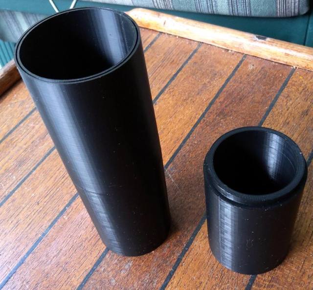
For funzies, you can just try printing a narrow tube in both orientations and try it for yourself.

Once again a really detailed , clear explanation … thanks for that. If I understand this correctly I’m thinking now that maybe I was very lucky not to have any layer separations. I remember that I re-printed all 3 after I discovered the “super-fine” settings in CURA and I wanted the finest surface available. They took a much longer time to print but are wonderfully smooth and needed only a fine coat of my fairing compound.

Sorry to hijack your query Mr Croquet.

1 Like

Prints are almost always weaker at the layer lines, often a point of failure. It is why so many change the orientation of prints to difficult positions so the layer lines are not aligned with the direction of force.

Stephen does a lot of this type of strength test. He usually prints samples flat and standing. It is clear very quickly how orientation changes strength.

Not to worry about hijacking the thread. All this is good learning. I was lucky enough to be told to lay down this part for a stronger piece. I’ve attached an sketch of the nature of the defect in the print. This is an end view of the piece. The flats are symmetrical and on both sides of the support material. I’ve gone to as much as 50 degrees on support with no change. If anything, I thought I’d encounter sagging layers not the opposite.

Any thoughts on how to correct it?

1 Like

I’ve always had good luck with tree supports, rather than a raft.

With the cylinder being only 16mm diameter and about 120mm long, is a tree support suitable? I thought tree supports were for taller & more complex prints. If you think it is better, I’m game to try. Here’s a screen capture of the part sitting in Prusa Slicer

Elbow-3D

I’m not aware of there being any real “limit” to tree supports. I’d say give it a try.

You are using a raft. Not just supports and skirt?

Is the part on the bed?

I print with the part slightly off the bed with raft and supports. I rarely see a flat. In prusa slicer I increase the distance of the support interface to 0.3 it is easier to remove. I sometimes increase the interface layers. Too.

Tree supports might help . I have never tried them with something so large.

The flats are very stubborn. After several other attempts at changes (tree support, angles, thinner layers) they just won’t go away. Is it appropriate in this forum to ask if someone with more experience is up to finding the correct setting that will round out my cylinder? If so, contact me and we can discuss it further. (croquetdon@gmail.com)

@Mr.Croquet I just printed a 20mm x 25mm tube. I used a raft and auto generated support material on the build plate only. It is round. Really ugly, it took 15 mins at 0.28mm layer height, very fast.
On the printer bed with raft.
IMG_4599
Separated from raft. round no flat spot. UGLY! :flushed:
IMG_4602
Settings from Prusaslicer it was printed with. You can likely transfer these settings to your slicer of choice.

That looks impressive, compared to my results. I’ll try your settings and let you know how it works. Although I’m relatively new to 3D printing, I started with the latest version of Cura but recently downloaded the latest Prusa Slicer.

A few other settings that I think may be crucial. I have used layer heights of 0.16mm & 0.20mm and speed of 80mm/sec What is your layer height and print speed on this?

Ok so the print is crude I wanted to be certain of what I was telling you was accurate. It is 0.28 layer height as course as I can get away with for anything. It was at 100 mm/s this is really too fast for this printer I was using it causes artifacts, but useful for quick drafts.

The setting that is important for your roundness is the raft settings. You need enough layers to fully support the starting point. 8 is this print. It was fully supported on the build plate. Typically a tube will self support. This is not always the case, ambient air temps and drafts may change that.

Your layer heights you can print well at will vary with your printer. My other printers don’t print well at 0.28 I don.t even bother. Others print faster speeds as they are more ridged. They are individual that way also two of the same mayn’t like the same settings.

SETTINGS ARE A STARTING POINT! You may need to tweek them.

I would strongly suggest when you have time and are not trying to print something specific, find a model that is not super difficult but isn’t really easy. and use that as a model to tune settings. Make a print change ONE thing (I make big changes at first) and see what it does. Many use a bench for this but I hate the waste. I printed tarp clips, something that if it was ugly it didn’t matter and you need a lot of anyway.

@Mr.Croquet I just wanted to see if you had success with a bunch of raft layers?

I recently printed a standing cylinder and it was printed 120mm tall 8 parameters and 20 mm diameter with a 11mm hole. It is very tough, depending on how thick your walls are and what application it might be tough enough standing.

Hi kitedemon,
Thanks for all of your helpful suggestions. In the end, I started testing by using a cylinder of the same diameter (5/8") and 1-1/2" long, lying horizontal. I also discovered that Prusa Slicer’s default settings just about cleared up the issue. A few tweaks to those default settings made were:

  1. ‘With sheath around the support’ unchecked allowed for easier removal from support material
  2. ‘Overhang threshold’ set to 40 degrees
  3. ‘Layer height’ is 0.20mm
  4. ‘Raft layers’ set to 5

Interestingly, when printing 3 parts at the same time, separated by about 3/4", one end of each was perfectly round while the opposite end, the cylinder distorted into an oval cross-section. My next trial for printing multiples will be to separate them far enough on the bed to print sequentially. Time-wise, it is very helpful to be able to set it to print an hour before leaving work for the day and letting it continue for the 5 - 6 hours required for 3 pieces.

For those interested in remotely controlling their printer for free:
I took an old smart phone and mounted it on the printer frame with a $5 clamp mount with goose neck that I found at the dollar store. This phone and my current cell phone had a free app called ‘Alfred’ installed. I can remotely monitor the printing and if it’s dark, the flashlight option can be turned on. Very cool and total cost under $5. If anything goes wrong with the print, I can log into my desktop, running the printer thru Ponterface and stop the print.

1 Like

That is curious. try turning them 90º on the bed. You could find on side it out. Some of the creality printers seem to have something out of square.

I have yet to find a suitable solution in the settings. I think I’m getting closer, having just viewed Youtube’s The 3D Print General’s video on ‘How to avoid needing support material’. Regardless of the support angle, the flats on the bottom of the cylinder show up where ever there is support (this could be a hint to the problem).

Using his suggestion, I slowed the perimeter speed right down to 15mm/s. That has had the most promising results yet. The only problem now is printing time has gone from 2 hrs to 5 hrs.