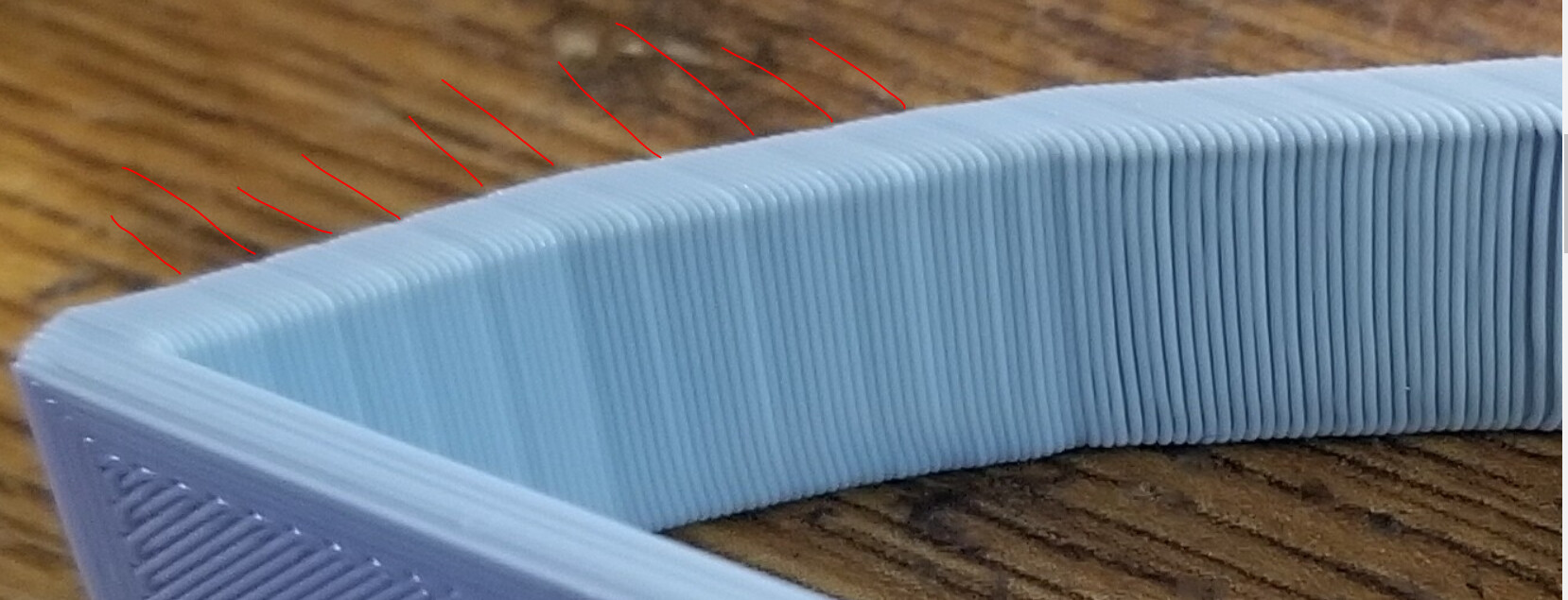
Can you take a really close look at the layers? In the layers where the walls are thinner, are the layers thicker? That would suggest the Z axis rose too much and the same amount of filament had to fill a deeper void and, hence, was thinner. Alternatively, if the layers are actually the same height, that would suggest the extruder is extruding less. But that would mean the extruder would have to be under-extruding consistently for an entire layer (or, conversely, over-extruding consistently for 6 layers).
Now, there is something I’m vaguely aware of. I wish I could remember exactly where I’ve seen this mentioned before, but I can’t at the moment… anyway, lets say, hypothetically speaking, that you have a printer with a selected layer height of .111 mm. Let’s further say, hypothetically, that the printer can only move in increments of .01mm…
So, the first layer would only be .11mm high - because that’s what the printer is limited to.
The second layer would be .11mm high… the top of this layer should be at .222 but is limited to .220
The third layer would be .11mm high … the top of this layer should be at .333 but is limited to .330
The fourth layer would be .11mm high… the top of this layer should be at .444 but is limited to .440
But the fifth layer would be .12mm high - the top of this layer should be at .555 but it gets rounded up to .560 and would appear as an extra deep (and under-extruded) layer.
Layers 6, 7 8, and 9 will be .11mm then the cycle will repeat.
As I say, I wish I cold remember exactly where the real-world example of this was, but it was due to a rounding error in the Z-axis gets made up for at regular intervals. Basically, it’s a disparity between what the Z-axis is being asked to move vs. what it’s actually capable of. That is to say, you must ask it to move an exact multiple of what it’s capable of. Anything other than that produces rounding errors that (I think) will manifest themselves as you’re seeing in the photo.
are you refering to the steps that the stepper is capable of ? in other words magic numbers ? and workin within those parameters ? as far as i know this is why most people use integers of .02 in their z-steps. i have always used this as a rule of thumb
i will have a closer look at the print and get back to ya, thanks for all the replies guys
just did an e-step calibration, and it was still good.
in regards to the thinner layer being higher its really hard to be certain however it looks like it is. i would hate to be wrong about that since it could derail troubleshooting in a wrong direction haha
I think Lego is on to something here. If you print an overhand calibration shape it will stagger the layers and make them easy to measure. Then we can figure out why it’s happenig
just had a thought, maybe its nothing but…if the hotend is not parallel to the X travel then, that could cause a different layer moving on X+ as opposed to X-, essentially it will be dragging filament one way but not the other ? i dunno, il add it to my list of things
well on mine if the Z-axis supports aren’t parallel ( and not racked ) I can’t level the bed. The nozzle is offset to the X-axis (cantilevered) so if one side is torqued back as it goes up in Z it’ll twist in the X motion. the mesh for automatic leveling relies on the Nozzle following a flat plane, I feel like that would only cause you trouble in big prints though. Yours seems to happen evenly across the prints you’ve shown.
forgive me this may be a little bit of a side step but, I did have this issue on a customer machine here at the shop. It was the Z-axis leadscrew that was touching the stepper motor shaft but not at a perfect 180deg. so the flex coupling was not able to work with the imperfection at the end of the leadscrew. every revolution it would “pop” back to as straight as it could get.
I loosened the grub screw on the coupler, moved it maybe a mm off the end of the stepper and tightened again. immediately the banding went away. the flex coupler couldn’t work in the particular was it was installed because there was about 15deg angle in the end of the leadscrew.
Don’t want to hijack the thread just thought about what I have seen in the past.
fair enough, it looks like you have already checked the common stuff which is why I didn’t wanna hijack the thread. I think Lego is going down the right path with troubleshooting. Just tossing my 2c into the mix
yes, they are spaced every 1.5 mm roughly. but that changes depending on the layer height. in this case my layer height is .2 if i were to print in .12 for example the bands would be smaller
not to my knowledge, this is why i was thinking if my hotend was skewed one way it would “wipe” one way and not the other. im still plugging away at this.
il doublecheck the direction but im 99% sure it always travels one way