my cr10 was printing beautifully, however after about 15 prints it started to show signs of random banding, in my efforts to reassemble and square/tram the printer i managed to get the banding fixed, but now i have ribbing that occurs every 10 layers or so. the ribbing doesnt follow the pitch of the leadscrew so i can see now thats not the issue.
at first i figured it was cheap leadscrew/nut so replaced them with better quality rods and an anti-backlash nut but the Ribbing persists.
full disclosure, i own a cnc machine shop and have aligned my machine to within 0.002" tolerance in squareness as well as setting the rods perfectly parallel,
but i am still at a loss.
I have a side by side here of 2 different layer heights, i have tried multiple slicers but it doesnt change anything.
printing with Sakata pla850 at 200c.
using cura for the image posted
side note*
I also monitored the pid during printing and it hold at 200c with minimal fluxuation so i dont think temperature swing are causing this either.
Could you post a side-by-side pic of the two samples? I realise you posted two pictures side-by-side but they may have been taken at different distances. What I’m looking for is the comparative size of the bands.
Also, I’m curious about how many layers make up each band cycle. It looks like 8 on the left and perhaps 9 or 10 on the right? Can you count them? Can you supply a photo of the entire model, top-to-bottom
If the cycles are all the same lengths then you likely have a problem with the Z-lead screw.
I realise you made sure the guides are exactly parallel but did you check that the Z screw(s) are actually straight (as in, not warped)? A warped lead screw will usually exhibit minimal banding when the print head is at the top and bottom of the screw, but the banding will be greatest toward the middle (of the screw, not the print).
If the banding is worse as the print head nears either the top or the bottom of the lead screw, it could indicate that the set-screw that holds the lead screw to either the bearing (top) or shaft adaptor (bottom) is loose or somehow holding the lead screw off-center.
Having said all of the above, I can’t help but think if any of it were true, it would produce a sinusoidal layering effect, but that doesn’t look very sinusoidal to me. Still, it’s worth double checking.
Mine did something like that once on PLA. I think it was starting to clog in the nozzle then it would sort of clear itself then start to clog again. it turned out my retraction settings were too aggressive and that was exposed when I started printing carbon fiber PETG because it clogged solid with that. I also had some matte PLA … pastel colour that clogged too and was resolved. I think there’s something like the carbon fiber in it to make it less shiny and that collects in the nozzle when it’s not optimal
thanks for answering LEGO,
im not at the printer until later today but, no the ribbing does not occur at the same heights, the distance between the bands seem to change depending on my layer height, its not following the pitch of the screw. im starting to think its a problem with 1 or both of the stepper motors, but thats just a shot in the dark. i indicated the leadscrews on y lathe, theyre pretty much perfect (within a few thou).
i had a closer look at some pics of the banding, it looks to occur at every 9th or 10th layer no matter the layer height, so the size of the band differs. also i printed a benchy last night to see how it would look with this artifacting. its clear to see the issue when the test print is just a repeating shape such as in the pics, but on the benchy it looks like a random mess.
Have you tried printing the 2x2cm hollow box with one wall thickness? What I’m wondering is: when the layer seems shifted inward, is it truly shifted (in which case an indent on one side will be a bulge on the other side of the same wall) or if it’s indented on both sides simultaneously (in which case it’s under-extruding)?
That is odd. Are the extruder gears ok? My guess and it is a guess is the extruder is skipping on a single point in the rotation. I would check the extruder gears if there is worn teeth (loosely teeth) or the grub screws are tight.
i had thought this might be it as well, also i checked that my filament was being pulled off the spool freely with no snags. i will double check the extruder though.
thanks
I had the same hypothesis but ruled it out since the only way to produce banding would be for the amount of filament needed over a full banding cycle to exactly equal a full extruder rotation. Aside from the improbability of that, on all but the thinnest models, it takes multiple extruder rotations to make one layer, not the other way around.
So, @Stokes, does the banding shown on the cube have the same spacing as the banding shown on the other models? Also, when I suggested the cube, I stated that part of the objective was to see how the banding inside the cube relates to the banding outside the cube?
Man, is this editor annoying. I tried leading spaces (they get deleted), leading periods (it allows either one or three, but not two), leading underscores (too wide). In the end I had to screen shot the editor.
do the move coordinates in the G code stack? like every corner where it changes direction should have a coordinate. z will be different but the X and Y should be long lists of the same point.
i checked the G-Code and yes, the coordinates stack.
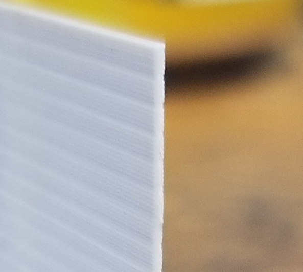
also i had some trouble determining whether the layers were shifted or of different width, so i made a clean cut on one side and i think the picture illustrates that the layers are infact different widths.