Ugh, I think I burned an output on this SKR V2.0 Board. Not sure how so I don’t know how to not do it again heh. So anyway does anyone know how to change the nozzle heat output to the second one available in marlin?
So the hot end output is on all the time as soon as the board powers up I get 24v on it right away, I also have CNC fan output for the part cooling fans. the output for that also shows as on (there are pilot lights on the board) but no voltage on the pins. I can do this burning out trick on one more heat output and 2 more fan outputs before nothing on the board works anymore.
In my limited experience, most MOSFETs get killed when someone cleans a hot-end with a wire brush with the heat being applied, thus momentarily shorting out the heating element and overloading the MOSFET.
If you have any experience with soldering, MOSFET replacement isn’t that hard - it only has three terminals - so that may be an option for you.
The second paragraph is a bit confusing:
The first paragraph refers to nozzle heat (3D printer, presumably) but the second paragraph refers to CNC fans, and if I’m reading it right, the power light says the fan is on but it isn’t running? Is this a secondary failure? When you say there is no voltage at the pins - do you mean the pins for the fan? I take it this is the heat break fan (which should be on when the hot end is powered) and not the parts cooling fan which only generally comes on at layer 2 or 3 unless otherwise programmed? Either way, I suppose the LED should track the fans behaviour. Generally, though, the LED should just be sitting directly across the output pins (with a current limiting resistor), so it’s hard to imagine how the LED is on but the power isn’t there.
well like I said I’m not sure what killed it. there are no shorts in any of the parts
that I’ve been able to find although the first board (the OE one) failed and the thermistor inputs were bad which I gather is a common occurrence on that V1.4 board according to PJ. I didn’t suspect any other failed part on this but there could have been, Now I’m using my own spare print head parts. I actually just noticed the cooling fans not working. no voltage (just trace. maybe 2 millivolts) at the pins and the output light is on. I managed to get everything working on this printer once, including the nozzle, bed heat, and thermistors, and I got this failure after a firmware update so I’m not even sure I did anything to cause it. When I was making the new firmware GitHub went down, when it came back online the last bugfix firmware wouldn’t compile, apparently, it had been broken for a few hours before I downloaded it, took me 4 hours to find out… so I went back to an older official firmware and in the middle of all that this issue showed up. The hot-end that’s on there now are all made of new parts of my own, not ones that I don’t know the history of so I’m pretty confident they are ok, they’ve all been used on my other printer.
The cooling fans don’t work from the software. the output is one of a programmable output called CNC 1-4 the old board only had one programable output for a fan. this one has four, I’m not convinced it’s set correctly in the firmware. I don’t see any feedback online about the B1 firmware with the V2.0 boards. They only recently started shipping that way so there isn’t much information on them even though this motherboard has been in the market for a while. They use pulse width modulation to control the speed of the fans on these outputs so it could be software causing it not to function even though it’s on. I don’t know how to look in marlin and see how it works
I don’t think I could if these are them. I think there are 6 spots to solder and it’s probably too fiddley for me and my giant soldering irons. I thought MOSFETs look like transistors with the heatsink on them but I guess there are different packages for surface mount stuff

They are transistors with a Drain a Source and a (sometimes two) Gate pin.
There’s a video here:

At the 3:00 mark, he removes a MOSFET using a clever technique I’ve never seen: folding a piece of copper wire around it to conduct heat to both sides at once. I’ve always done it by putting a ball of solder across the pins and moving the soldering iron back and forth between the sides. I’ll have to try this next time.
Of course, this assumes you can source the original part.
I had to replace this chip called a dallas clock on 100 ink jet printer units once. i was so nerved up doing that it put me off electronics altogether. these chips are much smaller and I see how this technique could make it safer to do for sure. but I have another output I can switch to if I can figure out the software, seems like less of a gamble.
Actually, I’m glad you posted this and made me look up the MOSFET. There is a shortage of these chips. and it causes BTT some trouble the chip I would need is numbered G090N06.
I would agree, then, that a firmware solution is your best option. I’ve never compiled Marlin so I’m out of my element, but I wonder if you couldn’t pull it off via Cura et al? Tell cura you have more than one print head. You may have to do this by adding a custom printer and giving all the same settings as your default configuration, except to tell it you have a second extruder. Then tell all the Cura setings to use that extruder instead. I don’t know if it’s that simple, but I’d start there.
Actually thats a great workaround.
other option is to just change the pins file swap pin A to Pin B and vis versa, then plug your device into the other plug in. Just make sure to note somewhere the file for the board is “repined”
this is what I want to know how to do. Actually I may get a replacement board from BTT, out of the blue they asked where I got it and the order number. it may have been defective. have you had trouble with them?
oh its actually pretty easy Give me a min and I will put up a post
so lets say you are using an SKR 1.4, in marlin you select your board as a BTT_SKR_V1_4
in the file called pins.h there is an association from board to Pins file
#elif MB(BTT_SKR_V1_4)
#include “lpc1768/pins_BTT_SKR_V1_4.h” // LPC1768 env:LPC1768
so now you know the pins file you need to modify is the files called “lpc1768/pins_BTT_SKR_V1_4.h”
now here is the tricky part;
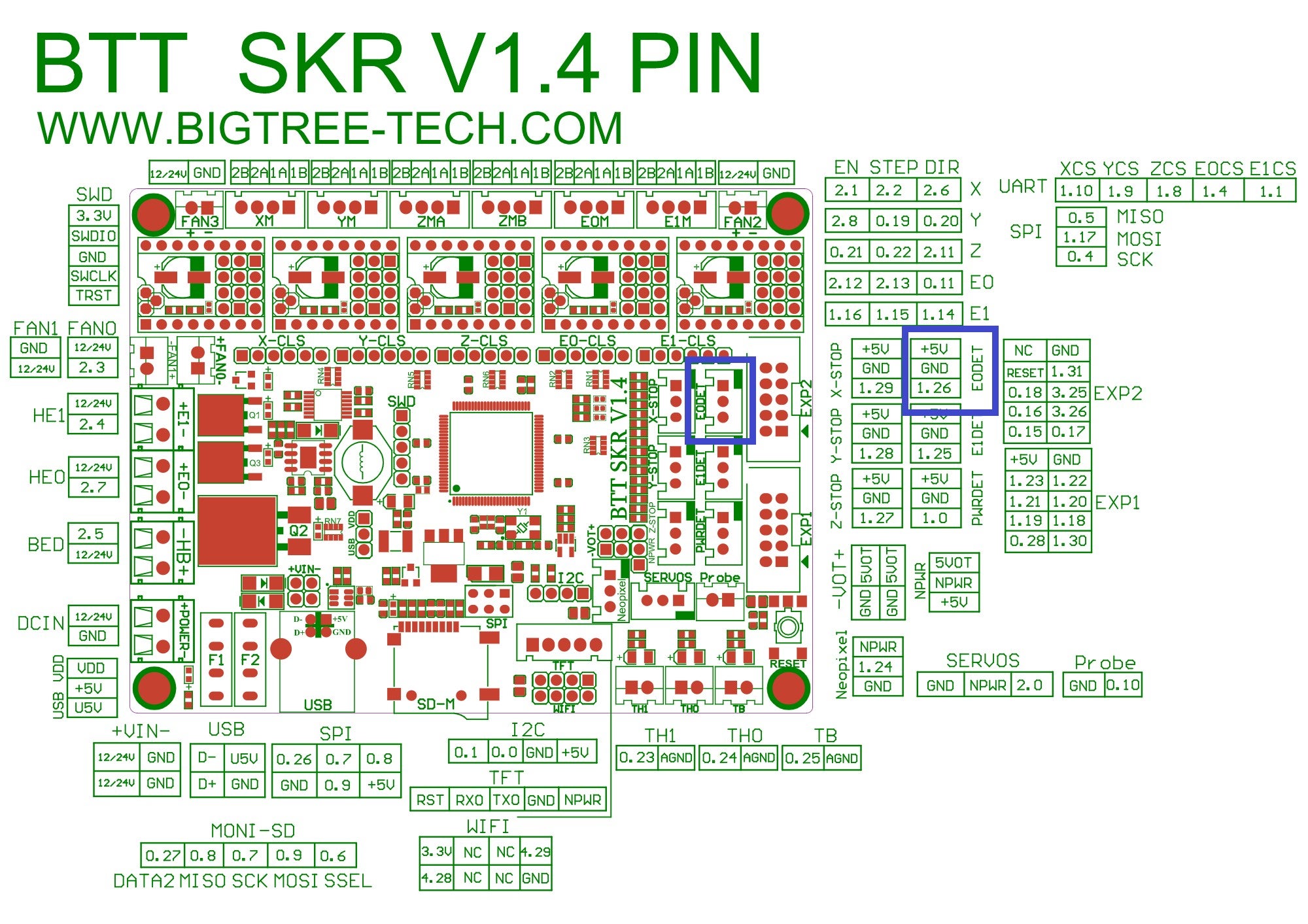
you have to look at the silk screening on the physical board, (or the pic from our website)
you notice on the highlighted plug and the associated pin layout there is +5V, GND, and a third pin called 1.26. This is the pin number of the associated control circuit.
Now open the Pins file mentioned earlier and search for 1_26 and you will find this
#define X_DIAG_PIN P1_29 // X-STOP
#define Y_DIAG_PIN P1_28 // Y-STOP
#define Z_DIAG_PIN P1_27 // Z-STOP
#define E0_DIAG_PIN P1_26 // E0DET
#define E1_DIAG_PIN P1_25 // E1DET
So Let’s suppose that the plugin question operated the E0 heater fan but for whatever reason, the plug failed. what you could do is move the plug to the one below it and change the E1 Diag pin to 1_26 instead of 1_25 and now you are using the plug below instead of the plug above. Just remember to change the 1_26 to 1_25 because you are not using it and it’s a dead plug anyway at this point.
You can assign and reassign pins as you which through this file.
Hope this helps
Jason
Thanks, i’ll have a look at these files later. the actual file you edit though is that done just in a text editor or do you locate it in visual studio code?
you can do it it either, I usually just use VS code as its in the tree under src
1 Like
Just getting back to this now. The board i’m working with is an SKR 2.0 I don’t thin this is the right pins file and I don’t see an SKR2.0 in the lists that are in the firmware
if you are using the BTT SKR2.0 you would use the following configuration
config.h
// Choose the name from boards.h that matches your setup
#ifndef MOTHERBOARD
#define MOTHERBOARD BOARD_BTT_SKR_V2_0_REV_B
#endif
Boards.h file shows the following
#define BOARD_BTT_SKR_V2_0_REV_B 4213 // BigTreeTech SKR v2.0 Rev B (STM32F407VGT6)
- so now I am going to look at this file and see what’s inside.
in the pins.h file you will find another step to the root file.
#elif MB(BTT_SKR_V2_0_REV_B)
#include “stm32f4/pins_BTT_SKR_V2_0_REV_B.h” // STM32F4
so in the file pins_BTT_SKR_V2_0_REV_B.h you will see this ref
#include “pins_BTT_SKR_V2_0_common.h”
when I search for this file is located in the following path
Firmware/Marlin-bugfix-2.0.9.2.x/Marlin/src/pins/stm32f4/pins_BTT_SKR_V2_0_common.h
Snippit from this file
// Limit Switches
//
#ifdef X_STALL_SENSITIVITY
#define X_STOP_PIN X_DIAG_PIN
#if X_HOME_TO_MIN
#define X_MAX_PIN PC2 // E0DET
#else
#define X_MIN_PIN PC2 // E0DET
#endif
#elif ENABLED(X_DUAL_ENDSTOPS)
#ifndef X_MIN_PIN
#define X_MIN_PIN PC1 // X-STOP
#endif
You should be able to match the ref “PC1” to the silk screening on the board.
In order to make sure you are modifying the correct file anyone looking at this thread you will have to follow all the named ref through all the files or you may end up modifying the incorrect file.
let me know if you need anything else.
in mine there is a pipe next to the #define so it’s
|#define MOTHERBOARD BOARD_BTT_SKR_V2_0_REV_B
Does that matter?
actually it’s not a pipe its some visual queue in the editor lol…
thanks that seemed to get it to work at least for the nozzle heat, I have to see about these cooling fans fan now.
LOL, sorry I missed your earlier msg, was working in the retail store for a bit.
Sometimes the formatting on the forum is a little misleading but I’m glad you got it underway.