I had the unfortunate event of a Bowden gap on an overnight print and my hotend was covered in a pile of melted plastic. This isn’t the first time this has happened with that specific hotend, so I decided to totally replace it.
I assembled the new end and powered on, then suddenly a spark at the hotend heater. The extruder heater must have had its wires too close together or crossed. I powered off immediately and adjusted the wires. Now the machine reads 88C on the bed and 82C for the hotend (both should read ~21C).
With the bed thermistor effected, I’m guessing that there may be a short in the main board.
Is this a cooked board then, or can there be something else replaced that can fix this?
Unplug the thermistor and verify that the temperature changes. If not, then you’ve damaged something on the controller board.
Having thought about it a millisecond longer, I realise that you’ve got false readings on both the hot end and the bed, so that sounds more like the voltage being used as a reference has failed. I don’t know for absolute certain, but I highly suspect that the thermistor circuits for both the bed and nozzle are powered from the same internal supply.
Without spending a lot of time researching it (which I suddenly don’t have much of and is the reason I’ve hardly been around for the last two months), I was able to find a circuit diagram that verified my suspicion that they use a common internal power supply but the circuit diagram was so grainy I couldn’t see what voltage was being used.
So I’m making an assumption here: Let’s assume the thermitors both get their power from an on-board 12V or 5V regulator on the controller board and that regulator is now shot. Look for a regulator (black plastic component with three pins and (probably) a metal tab. It would most likely be labelled either 78?12 or 78?5, where the ? could be an L or an M, and measure the voltage across the 2nd and 3rd pins when viewed such that you can read the part number. Pin 2 is ground (0V) and Pin 1 should probably read 24V, from your main power supply while Pin 3 will either be 5V or 12V. If it isn’t, replace the regulator (about $5).
HI @MattCTS
Welcome to the forum, Glad you found us. Any issues or problems you have post it up, Good group of people here that will give you lots of feedback.
Thanks for the detail.
I’ve taken a look at the main board and I can’t find any components labelled 78?12 or 78?5.
The only ones I see that have 3 pins and a metal tab are labelled with l4144 & GA3614.
Here’s a picture of the board and a close up of those components:
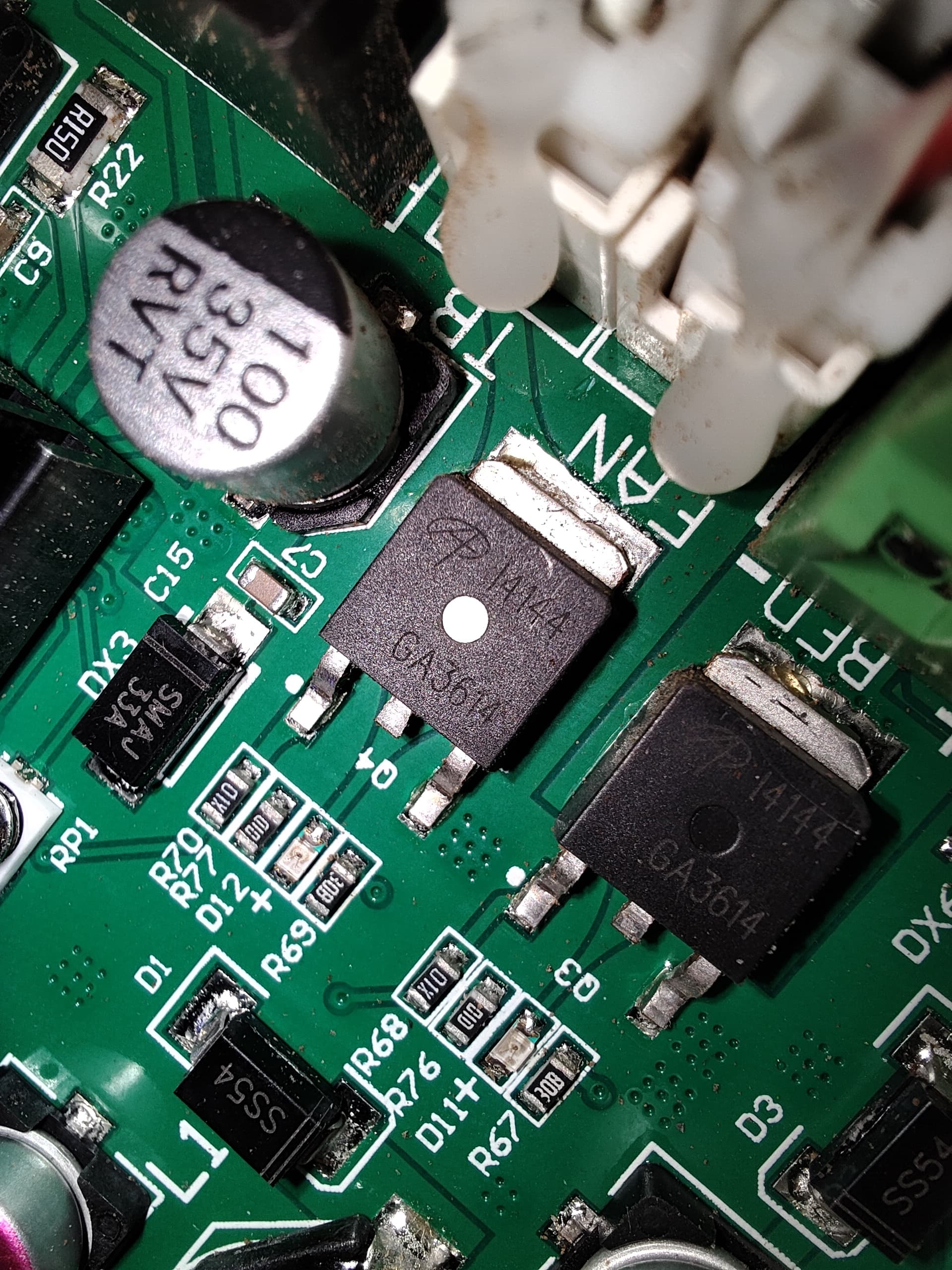

I’ve taken a reading they all read 24V over Pins 2 -1 & pins 2-3.
Would these need to be replaced, or am I not looking at the right thing.
Thanks!
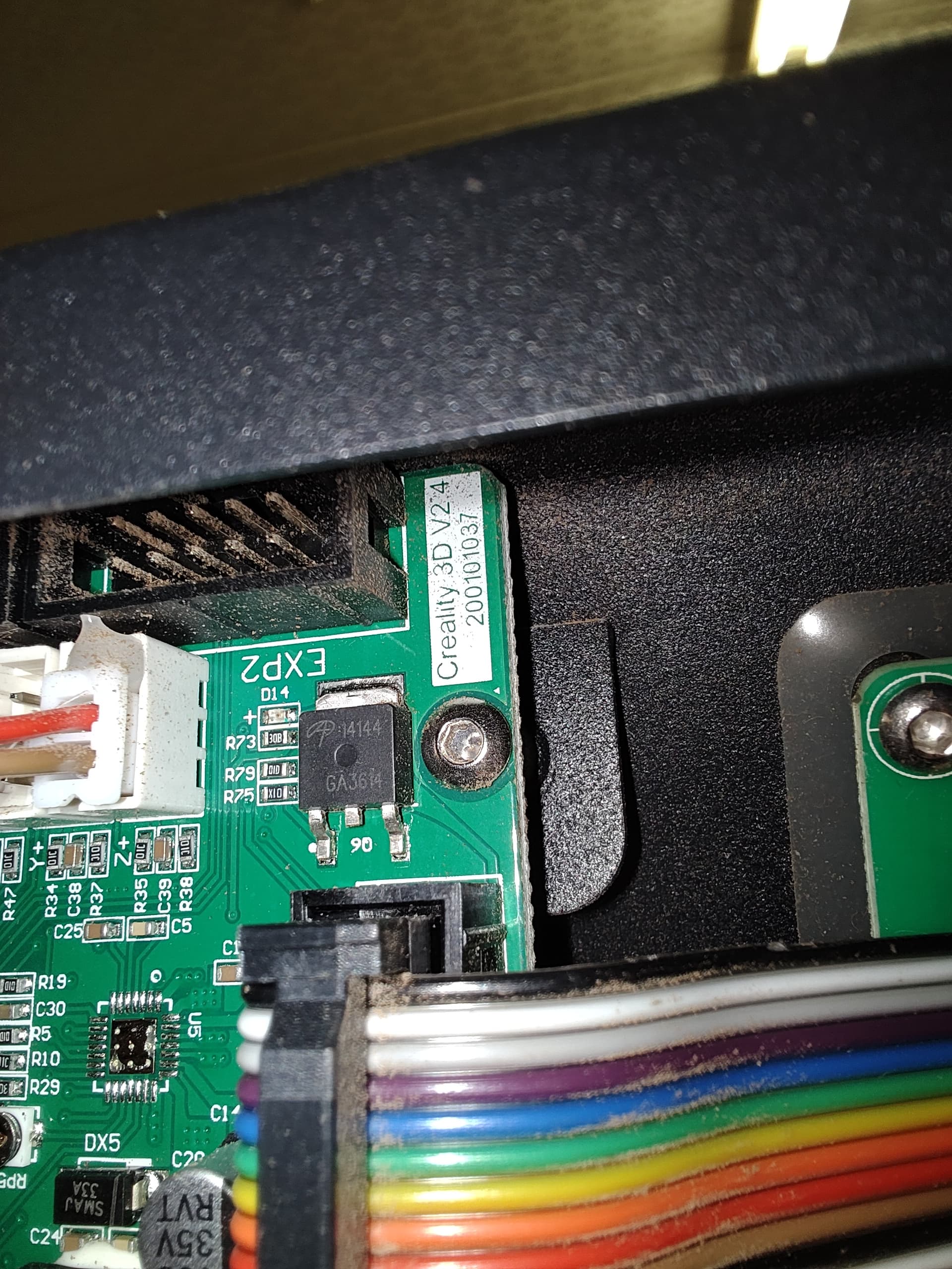
From what I can tell this is a Creality Version 2.4 control board from Maybe a CR-10Spro, Possibly a MAX but I am thinking right now it’s PRO. If you can 100 Percent confirm the version number of the board I have the Spec for it and can confirm the parts.
Right off the bat, I found this one;
It’s not from creality but it is one that a user has reverse-engineered, The ref voltage on the Thirm is 5V, 24 Volt input 5V out. If you are getting 24 on input and output that does confirm @LEGOManiac that the ref voltage is out and explains the off readings.
Did you confirm that if you unplug the Thirm that the temp will drop to some other predictable number?
I know I have the spec sheet somewhere for that board I was doing some reverse engineering on it a while ago. I will keep looking
So back to firmware I go, Board is ref as BOARD_RAMPS_13_EFB
config.h file ref the sensors as TEMP_SENSOR_BED and TEMP_SENSOR_0
This filters to end up on the pins_RAMPS_13.h file
Pins file translate those refs to pin # 14 and Pin # 13 respectively.
Just digging up the part number and location of the 2 components
OK here goes Your pic is attached and I have highlighted a couple of things,

3 units with the red dots are Mosfets, Basically tiny Relays from what I can find on the Ramps 1.3 board what you are looking to test is the component Dotted in Yellow next to the 10 pin. Its number is LM2596, Its a Buck converter in a single chip. Spec sheet below
It looks to be like the Thirm is taking ref voltage from pin 2 of this regulator. It is as Lego mentioned its the unit common to both circuits. and more than likely what got blown.
Hope this helps.
Just reading through everything.
It sounds like its the LM2596 that needs replacing, correct? (Yellow dot)
just looking at the specs that’s what I would think, Check it first and confirm against the schematic in the link. That will confirm it for you.
I do have the board in stock should something go completely south on you, Search for the V2.4 it will come up and CR10S Pro but you can reflash the firmware and it will work in a max.
Is this the one you’re thinking of?
Just want to make sure, will pick up tomorrow as I’m in the area then.
Do you sell the LM2596 as well, so I can try to repair the current board as a backup?
Yes, that’s the correct board, but no I don’t sell the components. Sayal in Burlington may carry them or newtech on Parkdale. I am pretty sure one will have it. Newtech has 90% of whatever I’m looking for.