Thread Strength Testing

This topic is copied from one I was writing for our Airgun Forum, I hope it reads OK…

I am testing a 1/2" - 20 TPI thread, printed vertically (in the “Z” direction)… I am printing five PLA thread test cylinders right now… I changed the design, separating the long and short threads with a 14mm cylinder…

The long, upper portion has a 45 deg. taper at the top, the other three ends of the threads are square, no countersink… The upper section is 25mm long, the cylinder 5mm, and the lower section 10mm, for a total length of 40mm, and a diameter of 26mm (increased a bit to give a full 6mm wall around the 14mm diameter center cylinder… I have put 5 models into Cura, and set 4 of them below the Platen by 2, 4, 6 and 8 mm, giving me coupons with 2, 4, 6, 8 and 10mm of test thread… This will give me an engagement depth to work with, and then I will try different layer heights… Just over 6 hrs. to print all five…

I still have to get and machine the end bolts… Just follow along!..

Bob

Well, I machined up the adapters today… So, once I had the adapters done (and 5/16" quick pins), I put the 2mm of 1/2"-20 thread sample in and it took 204 lbf. to break it!..

I then tried a 4mm thread sample, and I stopped pulling at 110 x 4 = 440 lbs. (200 kg.), which is the limit of my force gauge… One thread is 0.050" = 1.27mm, so the number of threads was 4 / 1.27 = 3.15 threads!.. Now we know that three 1/2"-20 threads in PLA will stand over 400 lbs!.. I am SHOCKED, that is over 100 lbf. per mm of engagement!.. Here are the samples and an assembled test piece (with only a 20mm OD, plenty strong enough)…

Top left is the 2mm sample after failing… Center is the 4mm sample, and it looks a bit beat up, but that was what it looked like after I chased the threads, which were done at 0.20mm layer height… Right is the 0.12mm layer height sample, which has also been subjected to 200 kg. of pull, and it looks and screws onto a bolt like new… NO permanent damage…

I’ll print up a few thin engagement samples in PETG to test, but all the rest of the samples I made are too much thread engagement for my setup!..

Bob

I have redesigned my thread test cylinder to 20mm OD, 25mm tall, with a 4 thread high (5.08mm) test section… I will be printing 1, 1.5, 2, 2.5 and 3 threads in PLA and two more at 3.5 and 4 threads in PETG, using a layer height of 0.158mm, which gives exactly 8 layers per thread… You just drop the model down below the Platen to print fewer threads…

The printing time is just over 30 min. per cylinder… The object is to produce a strength graph for each filament, with force to fail plotted vs number of 1/2"-20 threads… It should be a straight line, of course…

Bob

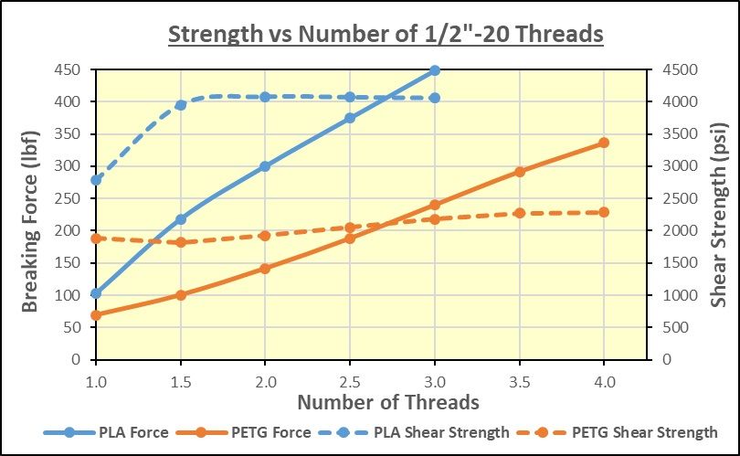
I ran a set of thread tests today, 1/2"-20 threads printed at a layer height of 0.158mm (8 layers per thread) in both PLA (Overture Grey) and PETG (Overture Black)… I tested 1, 1.5, 2, 2.5 and 3 threads in PLA and those plus 3.5 and 4 threads in PETG… I could not test more in the PLA because it would have exceeded the limits of my Force Gauge… Here are the results…

The PLA took about 150 lbf. per thread to break, and the PETG took about 80 lbf. per thread… A single thread is not very reliable for data, as one might expect, but from 1.5 threads up, the data is pretty linear, as you would expect… The dotted lines give the Shear Strength in psi, based on the calculated theoretical area of threads in shear (number of threads x pitch diameter x PI x (pitch/2))… The last number is the theoretical thickness in shear of one thread at the pitch diameter… For 1/2"-20TPI that works out to 0.0368 sq.in. per thread in shear… In theory, those should be straight, horizontal lines (the shear strength should be constant, independant of area)… They are pretty close, so that validates the testing method…

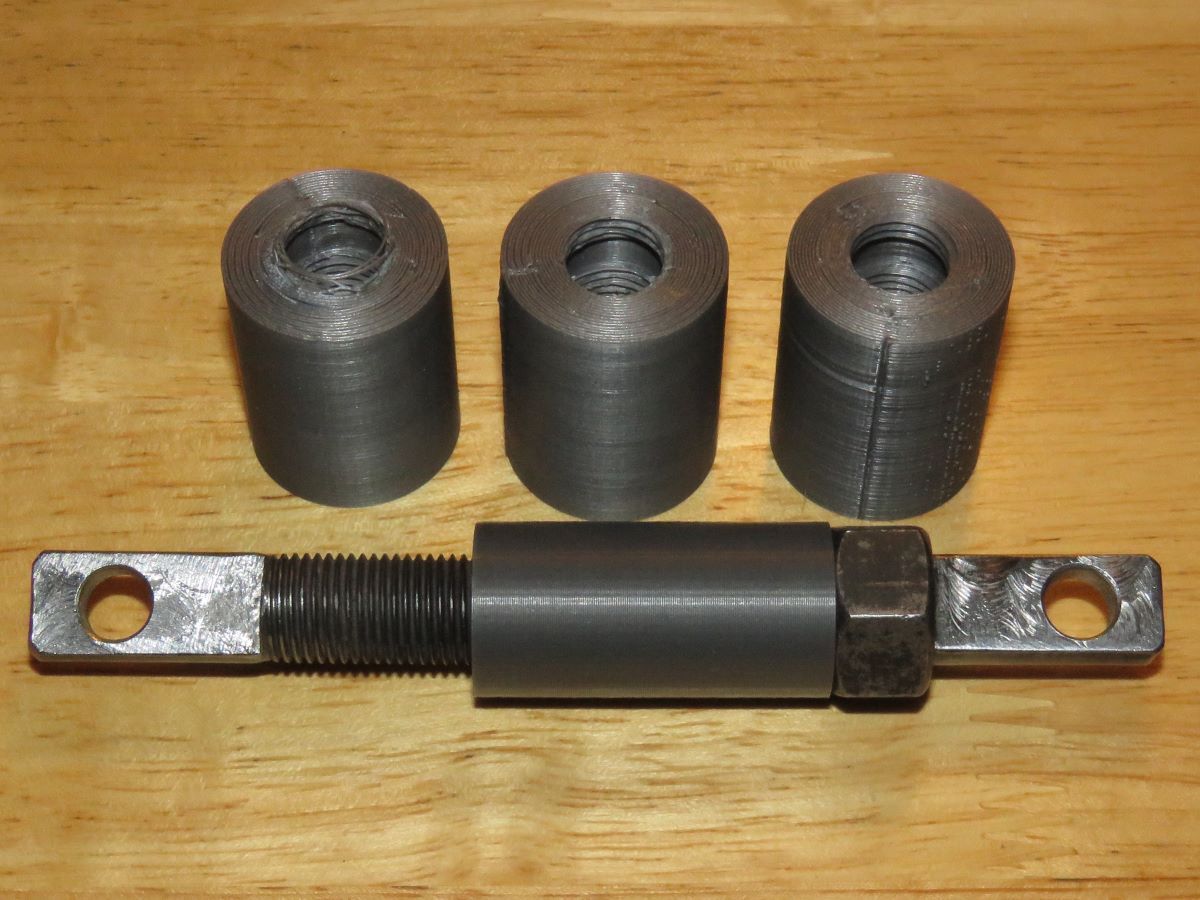
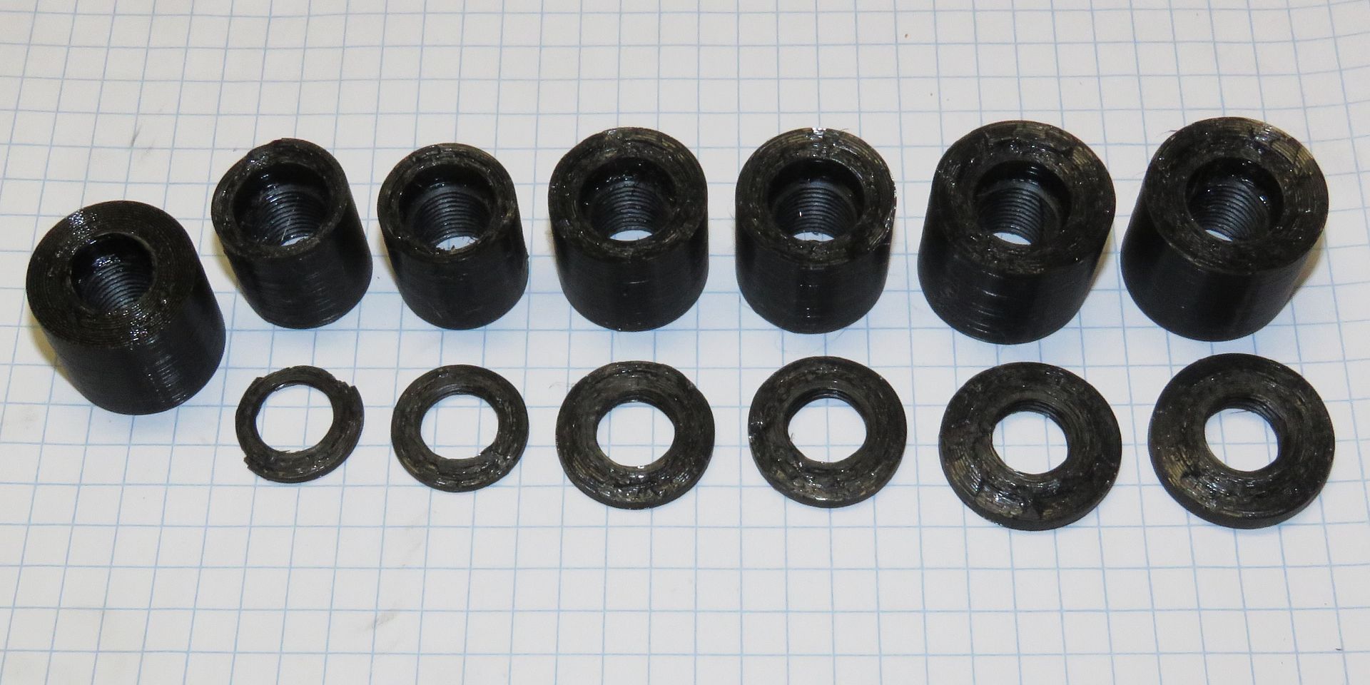
I took photos of the broken test cylinders, and the results were interesting… First the PLA…

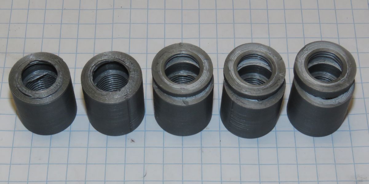
and then the PETG… Both photos had a single thread on the left, increasing in thread count to the right… Click on the pics to enlarge…

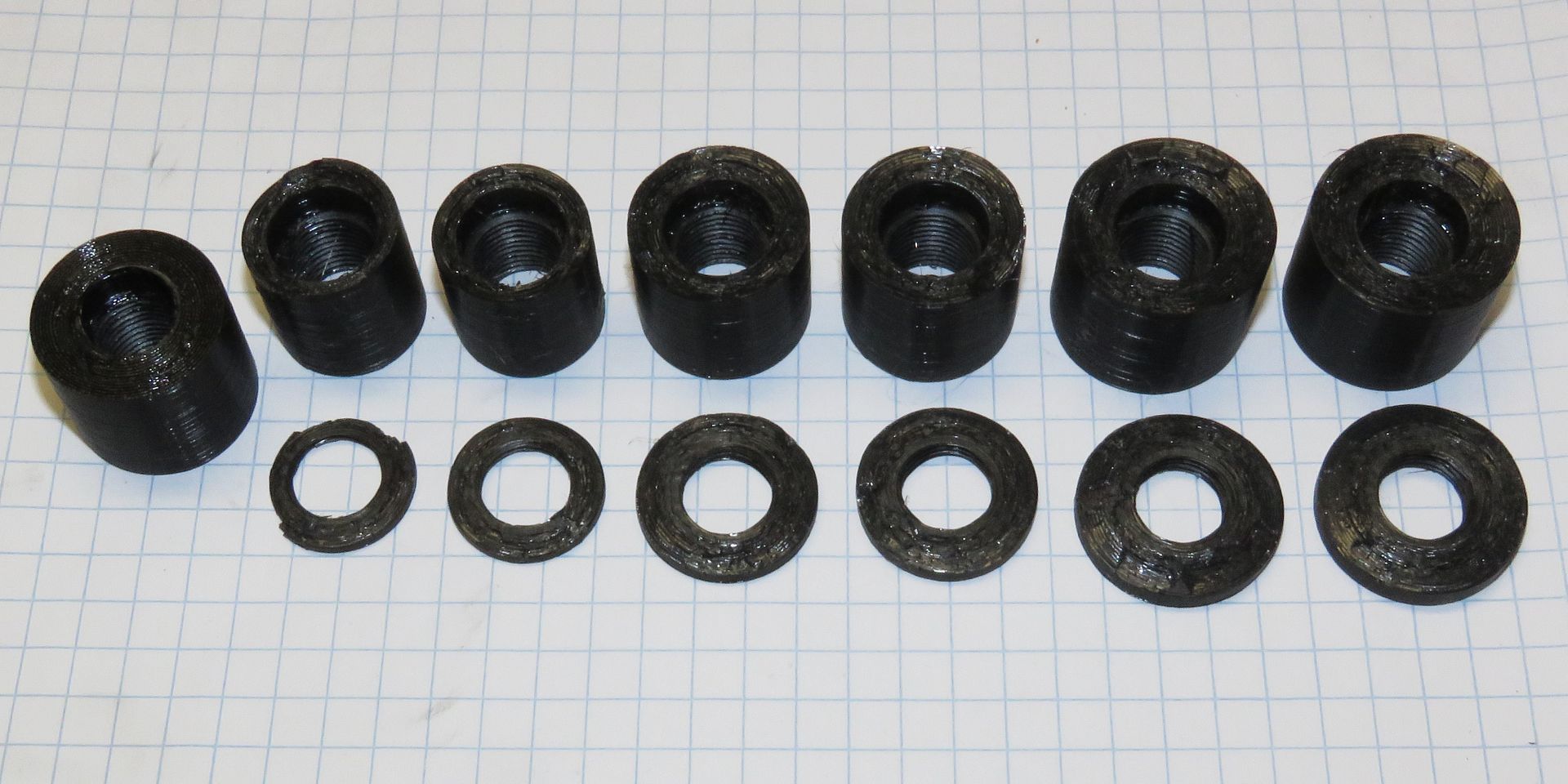
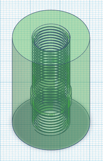
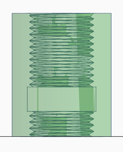
In all cases, other than the very thin thread samples, the failures occurred right where the last thread stopped, where a 14mm diameter internal cylinder provides a precise location where that occurs… The test threads were between that 14mm ID and the outer end of the test samples… Now one might think that showed that the wall of the cylinder at the 14mm diameter was too thin, causing the part to fracture there… In fact, with the PETG I made the OD larger as the thread count increased to help avoid that, to no avail…

I went back and checked my calculations on that portion of the cylinder, and recalculated the theoretical breaking force, using my measured tensile strength in the “Z” direction for these two materials… The area of that cylindrical portion is (20^2 - 14^2) x PI/4 = 160 mm^2 = 0.248 sq.in… The Overture PLA had a tensile strength of 4750 psi when printed at 220C (which is what I used for the thread test), which should take (4750 x 0.248) = 1178 lbf. to break, requiring nearly 4 times as much as the 300 lbf. it took to break the middle sample, which had 2 threads… The Overture PETG had a measured tensile strength of 3650 psi at 240C (the thread printing temperature), which would take (3650 x 0.248) =905 lbf. to break, over 9 times the 100 lbf. it took to break the 1.5 thread long sample… Additionally, if it was the wall thickness of the 14mm ID section that was the weak point, it would have failed at the same force in every test, which it did not… Also, the thicker cylinders I used for the longer threads in the PETG samples, would have showed an increase in force required to break them… The largest OD samples I used were 26mm, having a cross sectional area at the 14mm ID more than double that of the 20mm cylinders…

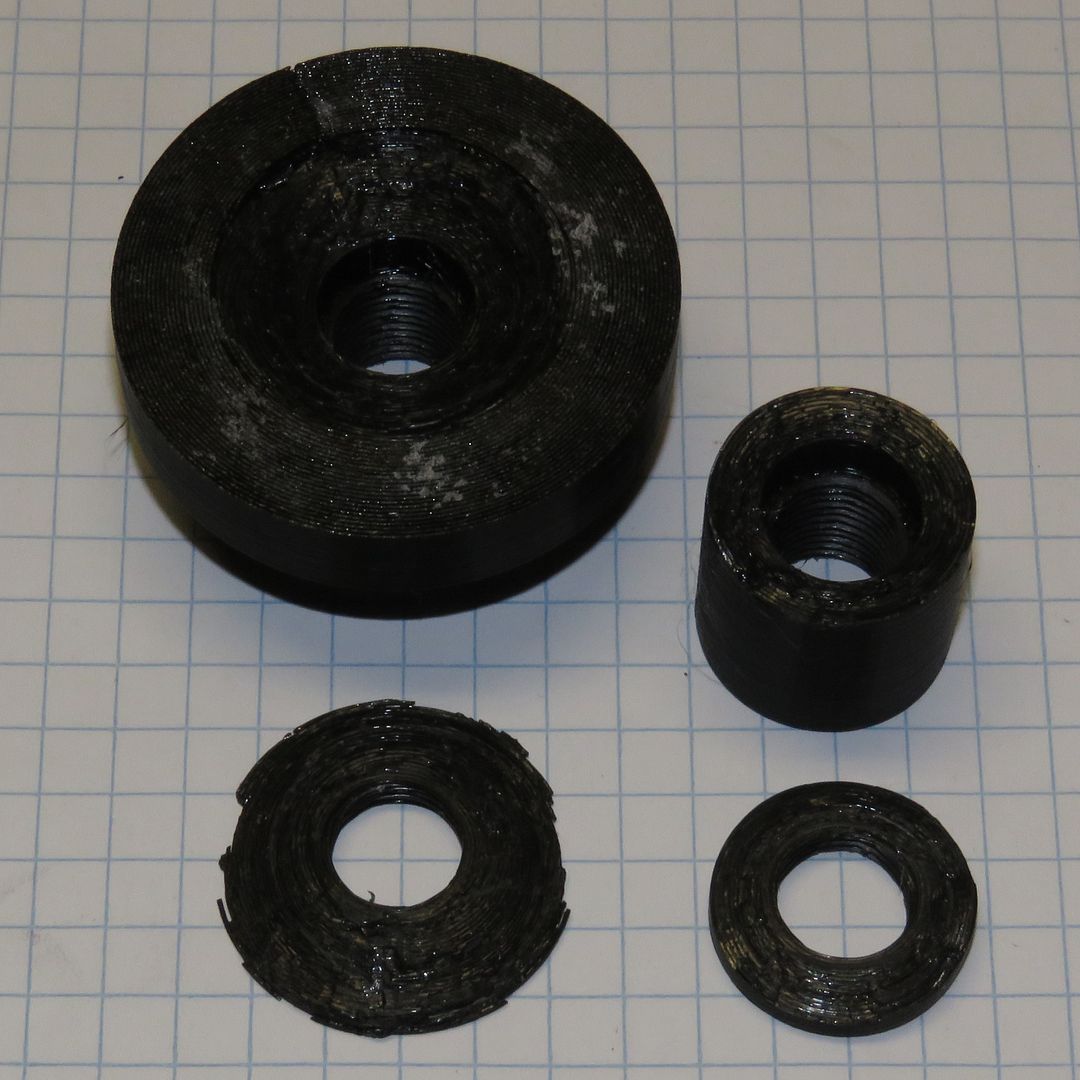
So, how are the samples breaking?.. If you look closely at the thicker thread samples in PETG (right end) you will notice that the samples broke along a cone shape, and did not simply rip between the layers… None of the samples (except the very thinnest ones, which stripped out) broke anywhere but at the inner end of the threads, which of course is where the stress is the highest… Although every thread imposes load on the cylindrical wall outside of it, those loads add up and peak where the threads end at the 14mm ID recess… Therefore, that is the point that tears first, and once that rip starts, it just zippers across the outer tube, following the line of maximum stress, which is supported less and less as each layer of the print breaks…

The fact that the data behaved exactly as it should, and that the Shear Strength was less than the Tensile Strength of the material (in the Z direction), I think these are valid and reliable tests… How thick an outer structure would you need before you would see even 4 threads pull straight out the end?.. I dunno, but way more than the 6mm wall in those 26mm OD samples…

Bob

1 Like

OK, curiousity got the better of me, and I did one more test with a cone-shaped test piece, 50mm at the base and at 11mm up, tapering to 24mm at the top (25mm high)… It was PETG with only 3 threads, and took 340 lbf. to break… and it broke in a way I did not expect!..

I should have known that is what would happen, comparing it to the previous test with 3 threads, which broke at 240 lbf… They both broke in a shallow cone, with the deepest part at the bottom of the test threads, right where the tension is the greatest, and tapering up towards the end where the bolt was inserted… In the case of the 23mm diameter cylinder (on the right), that left a tapered “washer”… In the 50mm diameter test cone, it ripped out a tapered wafer, where the OD was between 30-32mm in diameter… The original sample, tested above, was limited by the OD, but the cone was limited only by the depth from the bottom of the threads to the end… Having those 3 threads set down further from the end (or having more threads, so that the bottom thread was further from the end) would increase the difficulty in tearing that tapered piece out, and very likely make it larger in diameter, following more or less the same angle, which is roughly 20 degrees… The ultimate strength was roughly proportional to the OD of the tearout… (32 / 23) x 240 lbf. = 334 lbf. and the cone failed at 336 lbf… Coincidence, or maybe a rule of thumb (for the same number of threads)?..

Following this logic, a 2" diameter solid (100%) print of PETG would support about 6 threads before the cone torn out would reach the OD and the strength then start dropping because the tear-out becomes affected by the OD… That should happen at about 680 lbf., using double the 3 thread of this test piece… Call it 100-110 lbf. per thread for PETG, but limited by the OD of the printed part splitting along that roughly 20 degree angle…

All of this has too many variables to be relied on for safe design work… but it is VERY interesting to know that the limiting factor to thread strength is for the most part the OD of the part the threads are in… If the part has Infill, the the diameter to where the infill starts would become important…

Bob

Thank you for sharing! Great results and repeatable - well done.

I am surprised at how strong printed threads in pla can be.