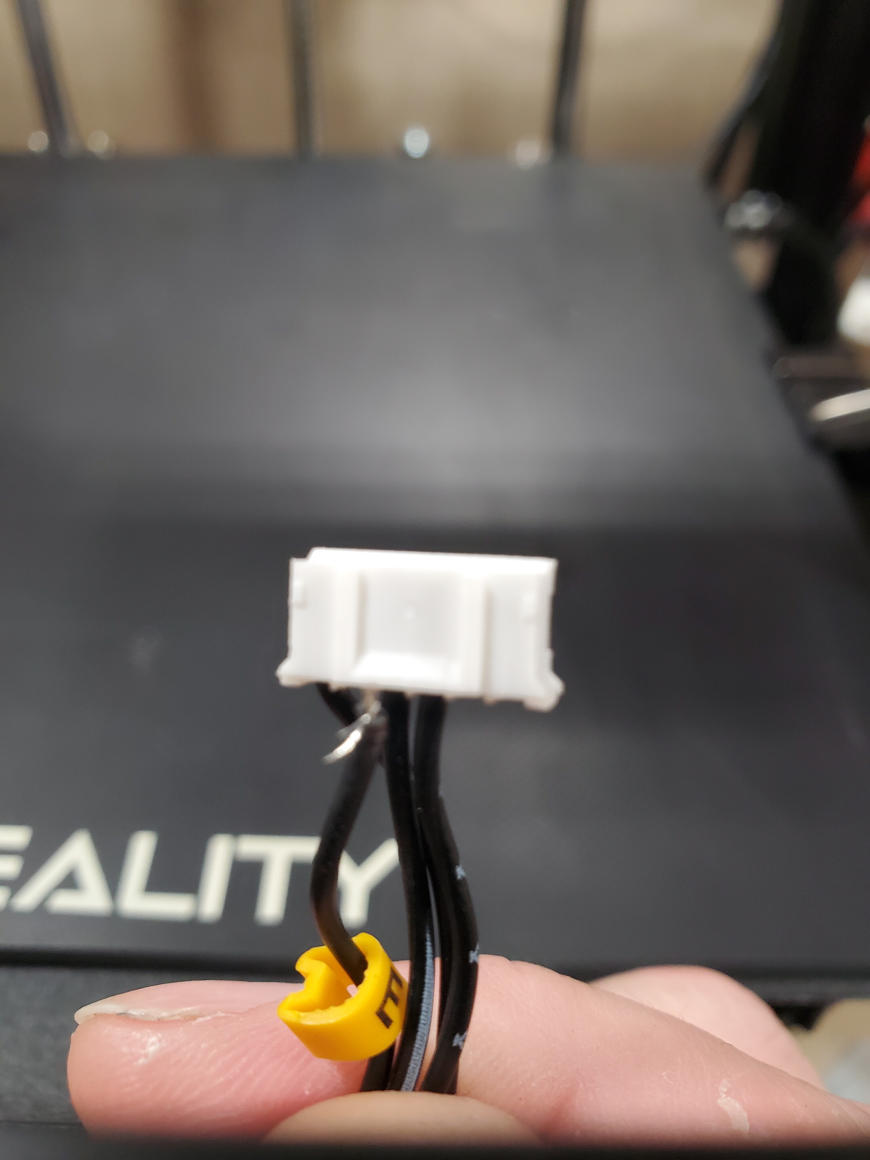
If you could photograph the top and bottom of the separated connector, that might help me. I don’t recognise this particular style connector from the back so I’ll give you advice based on connectors I am familiar with…
On second thought, I’ll save more for when I see a photo, just in case I give you advice that leads you on a wild goose chase.
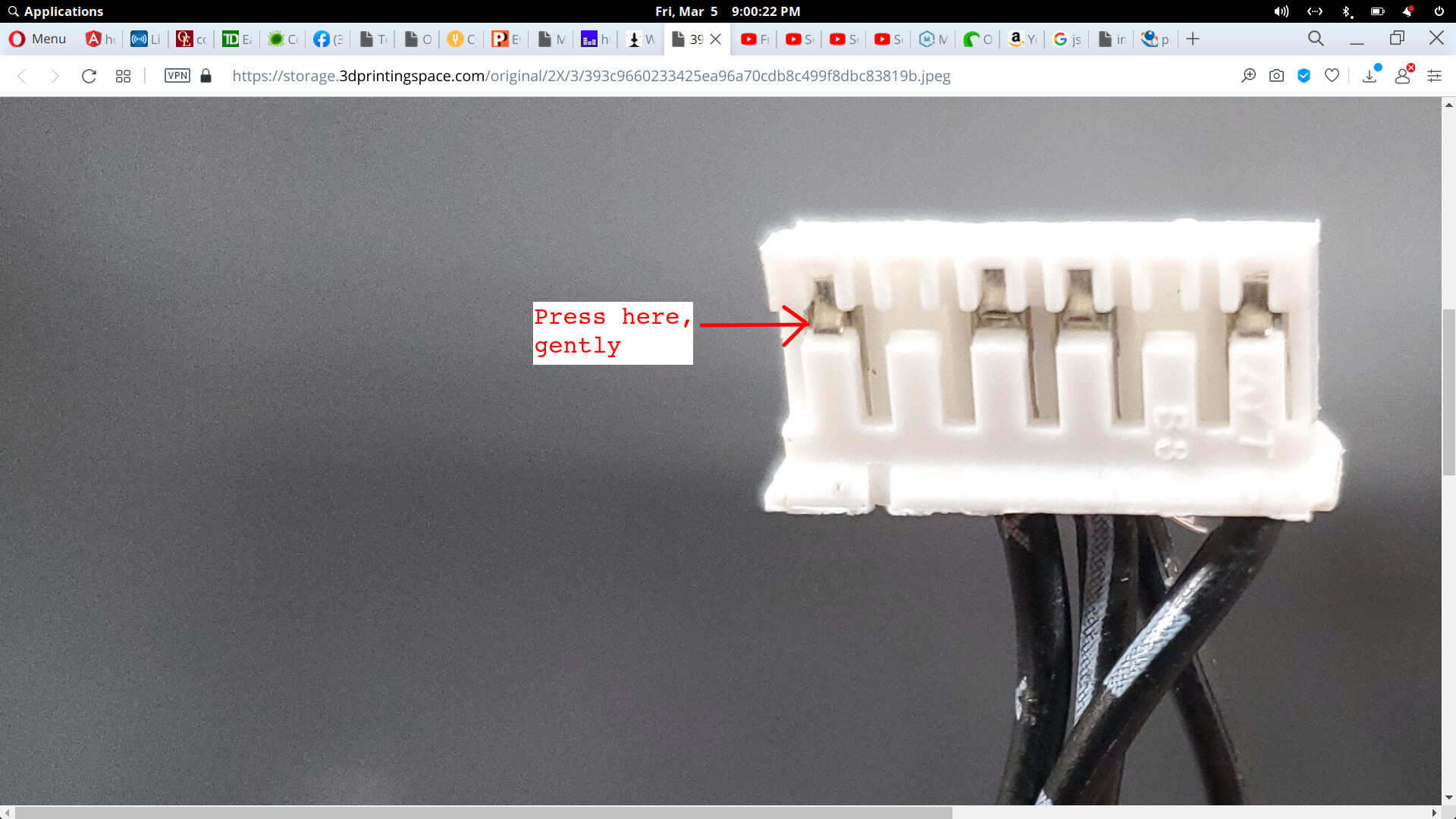
Use a sewing pin or something similar to puss on the metal tab where the arrow points. Be gentle. You’re trying to nudge it, not kill it.
Press at the side of the tab closest to the plastic that’s holding it back. Once you’ve pressed it in past the plastic, the pin should hopefully slide downward (in the photo’s orientation). If not, you may need a second pin to push the connector’s pin down while keeping the tab down.
Note: if you push the tab too far, it won’t spring back to latch again when you re-attach the wire. The wire will just randomly fall out, connector pin and all. Also, if you press too hard, the pin may snap off. They’re not designed to be flexed too often.
Once the connector pin is out, I’d suggest soldering the wire to it. In fact, you may have to since the metal part of the wire was probably crimped to the connector and is probably still in there.
Unfortunately, the critical part is out of focus, probably better if you had photographed it 90deg to the pin.
To answer your question, yes, that’s how it’s supposed to be done. There are two crimp points in these connectors. The copper is supposed to go through a loop about half way down and get crimped there, and the insulation is supposed to be crimped at the end. The reason being that people tend to pull connectors by the wire and if you don’t crimp the insulation, the insulation can be pulled back exposing the copper which can then short against something else another wire or a frame or whatever. So, the end crimp holds the insulation in place while the middle crimp is the actual electrical connection.
I would absolutely solder it. As you’ve already learned, crimped connectors are just asking for trouble. They’re really meant for cases where people aren’t going to fiddle with them, which applies to a lot of people, but for those who like to tinker with their printers, definitely re-solder anything that comes loose.