I’ve had my CR-20 Pro for about a year. There’s not a lot of love out there for this printer but it can make some impressive prints.
I immediately set up a Raspberry Pi with OctoPrint and got a 1080P web cam to have total remote control. I can watch the print from anywhere in my house.
I was spending a lot of time trying to get prints to stick to the flexible magnetic sheet that came with the printer so I bought the Creality glass plate which I’m very pleased with. I use the top side and have not had issues with PLA but I sometimes use have issues with PETG - but I’m new to this material.
As the weather got cooler and I print near a door, it was time to invest in an enclosure. I looked at the fun DIY projects but settled on the Creality made fabric enclosure. It’s great to stop warping of prints from a draft and keep the dust off. The kids an see what’s printing and I don’t have to worry about them getting burned. The temperature inside gets to about 37 and humidity drops to 15%. It’s a good time to dry some filament that wasn’t packed away nicely.
In November my extruder release lever broke which gave me the excuse to upgrade to the Micro Swiss Direct Drive Extruder with All-Metal Hotend for CR-10. It introduced zebra banding or salmon skin into my prints. I was in a panic to get Christmas presents done so didn’t try to fix it with the Creality board. Instead of bought the SKR mini E3 V2 board which solved the problem immediately. This SKR board is so quiet I can’t tell when the printer is actually printing and it sits behind me all day! I love how quiet that is.
In an effort to reduce fan noise, I picked up some 5015 blowers and a 4020 fan. I’ve just installed a fang style cooler and now have to do some retuning. The fan noise is less than before but not significantly like the stepper drivers in the SKR board. I stayed with 24V fans. I’m worried the quiet 12V Noctua fan can’t cool enough at higher temperatures.
CR-10 FANG dual 5015 and BLtouch for MicroSwiss direct drive by bogdi1988 on Thingiverse: CR-10 FANG dual 5015 and BLtouch for MicroSwiss direct drive by bogdi1988 - Thingiverse
Next up is integrating a filament run-out sensor into the Pi, setting some colour changing LEDs to indicate status of prints, building a dry box, and use my Neural Compute Stick 2 to detect print problems.
Looks like we went down similar paths.
I immediately upgraded the board in my CR-20 Pro as well as the display because I wanted quiet steppers and a 32 bit board so I could change firmware more easily. I designed a case for the new display that magnetically attaches to the printer body and the cables run into the opening from the old display through a locator pin that holds the new case in place.
I also swapped the magnetic bed for the glass one right away.
Then I had problems with the stock extruder skipping and the bowden coming loose so I also installed the MicroSwiss direct drive with all metal hot end.
I figured with the extra weight of the MicroSwiss it wouldn’t hurt to constrain the gantry a bit more and do dual z.
My OCD hated that the stock spool holder was so floppy so I printed a new one that spins on a pair of repurposed 6806 bearings that I had sitting around from a bicycle and designed some conical wedges to adapt to different internal diameters of spools.
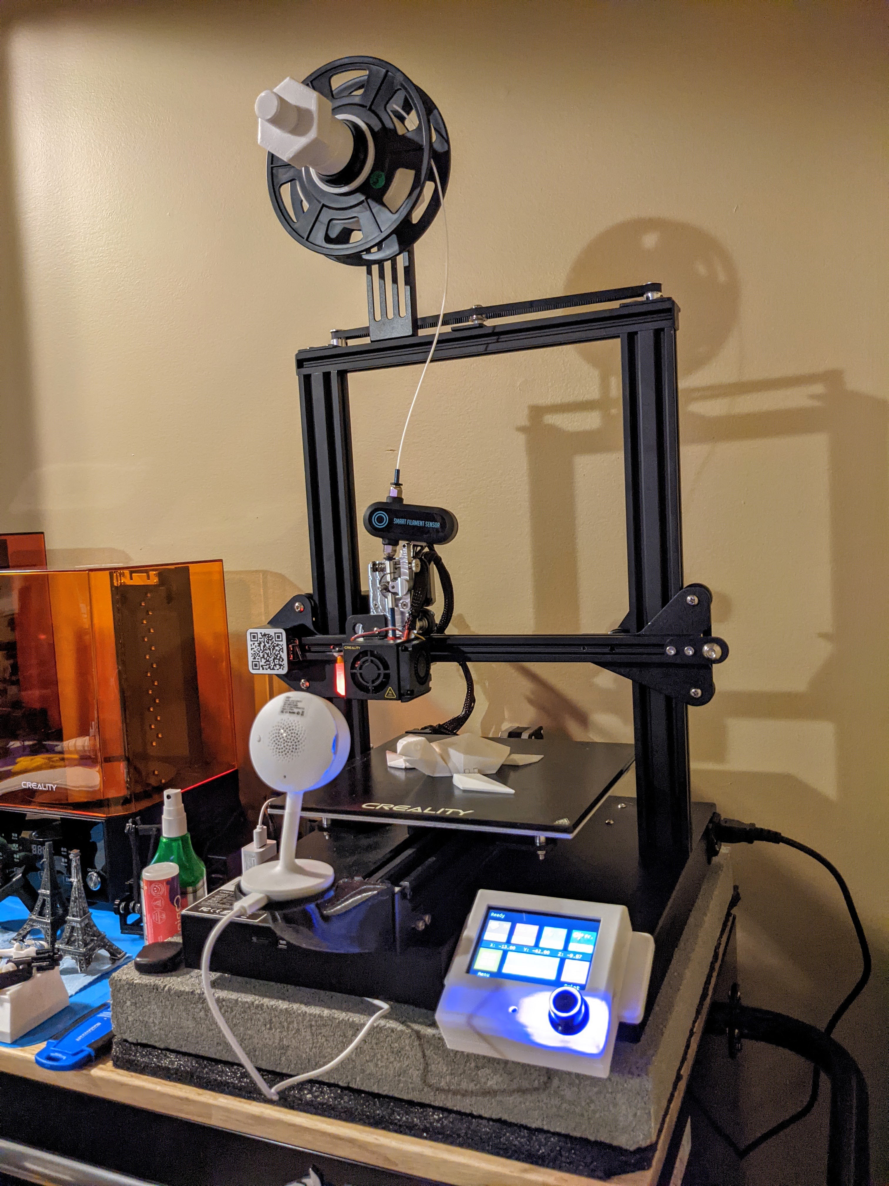
Finally I added a smart filament sensor and designed a mount for my wifi webcam. I haven’t gone down the Raspberry Pi route with Octoprint but for now the printer is plugged into a smart outlet so if I need to I can kill the power to it when I’m at work.
I’m also thinking about that Creality enclosure to help with warping on PETG from drafts and my cold Canadian living room.
Still on the list is a BTT UPS Power Detection Module, and an enclosure. I might also try a pancake stepper for the extruder since it would be better for weight and the full size one made me lose about 30mm of Z height.
Hey guys, I know I am a little late to this forum, but I too own a CR-20 Pro. I would really like to do the upgrades you guys did to yours. I have modified firmware but only basic stuff, just enough to upgrade to Marlin 2.0. Other than this, my CR-20 Pro is stock and begging for some upgrades. If I was to add the BTT SKR E3 Mini V2, Micro Swiss Direct Drive Extruder, BTT Smart Filament Sensor, and BTT Display, what needs to be changed in the firmware?
If you switch all of those parts you would basically have the same machine as mine so the firmware would be the same. I did add a tft35 e3 v3 display since it was a fairly cheap upgrade and is much nicer than the stock one.
The display might be the only thing that would make my firmware different from the upgrades you mentioned.
It was a while ago that I did mine but off the top of my head the only firmware changes were for setting up the bltouch, selecting my display, and enabling the smart filament sensor. There are sample configuration files for marlin for the btt boards for ender 3 and I just based mine off of that. The other things that need to change are things like home offsets, zprobe offset, e-steps which I did update in my firmware but can changed on the machine afterward too. Don’t forget to pid tune the hotend and bed as well.
If you do proceed with all of this and do the tft35 I can send you my firmware as well as a model for the magnetically attaching case for the display.
Swapping out the board to the skr mini e3v2 also meant a few of the plugs needed wires swapped around and I do have some pictures of mine when it was all done for reference.
Wow thanks, I currently am battling with my print bed not staying level. I figured I would have a go at UBL so I recompiled some firmware this morning. Should I use PID bed for this printer? How close is the CR20 pro to the Ender 3?
I was thinking of doing the upgrades closer to Christmas so I will keep your offer in my mind. Thanks for being willing to share your STL file, firmware, and pictures with me!
When I mention PID I was referring to tuning the heating algorithm that controls how it knows when to turn the heaters on and off to maintain a steady temperature. It is something you do when you change components that would affect the heat such as installing a new hot end or when I switched to a glass bed from the thin magnetic one.
As far as how similar a cr-20 pro is to an ender 3, they have a lot in common. The cr-20 came with better Capricorn tubing, Gates belts, and a different chassis. None of those things make any difference to the firmware and electronics.
On the electrical side the main board and display in the cr-20 are from a model of cr10 I think, and the bltouch is installed.
So when switching to a different board like an skr mini e3 which is meant for an ender the only real difference is that you’re basically just using an ender 3 with a touch probe.
I did remember one reason I changed my display to the tft35 when I changed the main board. The stock cr-20 display plugs into two of the larger EXP1/EXP2 ports and the SKR Mini e3 v2 board only has one of those plus a different shape port for the TFT. Looking at the original post it looks like the stock display still works but I didn’t know when I did mine.
Microswiss teased a new extruder on their Instagram recently that they said is coming soon so if you’re waiting a bit before doing upgrades the new one might be out by then anyway.
I have a SKR Mini e3 coming in the mail tomorrow. Just my luck that the extruder stepper driver crapped out and thus why the new board is showing up tomorrow. If you are still willing to share those files and wiring diagrams, it would be much appreciated.
I followed the video from Teaching Tech when I did mine and used STM32F103RC_btt_512K for the environment.
Perhaps it is slightly different now since there should be a newer version of Marlin than the one I compiled with.
Here is a link to my firmware for both the board and the tft 35 e3v3. There is a precompiled .bin file in the .pio folder - it is likely some of the settings are going to be different for yours if you haven’t switched your display or extruder yet. https://drive.google.com/drive/folders/1PvoHKwajK0oMv2MbXYOy_ZzRZLcipd4f?usp=sharing
I just looked back at the old photos of my board and they are pretty unclear so I don’t know if they will be a whole lot of use.
I do remember that I had to switch the pin orientation for both the Dupont plug for the BLTouch as well as the JST plug for the end stop for the BLTouch.
Looking back at the photos I think the stock orientation for the BLTouch Dupont plug was Yellow-Red-Blue. The ribbon cable however is Yellow-Blue-Red so the stock Creality orientation had Blue and Red crossing over each other going into the plug. For the BTT board they should not be crossed from what I remember.
Then for the White/Black wires going into the Z end stop plug they should be switched as well. Without switching them the BLTouch would turn on and boot properly but when it was probing it would just drive the nozzle into the bed.
Other than that the wiring is pretty straight forward and that Teaching Tech video gives a good rundown on the steps.
I am having lots of trouble. The firmware keeps saying how 5v of not compatible with z_min_probe among a whole bunch of other problems.
Switching to a slightly older marlin seems to work but it does not allow me to upload firmware to the board via USB.
I have always installed the firmware by putting the .bin file onto the micro SD card, it will automatically install when you turn the printer on.
As far as the 5v issue, I’ll try to download a new copy of marlin to see if it throws the same error with my configuration files. I certainly fought through my share of headache when I did my board swap since I am far from an expert on this topic.
So I downloaded the current version of Marlin (2.0.9.2), then compared the configuration.h and configuration_adv.h files from my old version and moved all relevant changes from the old files into the new ones
There were a couple of things from my old configuration that threw errors while trying to build the new one.
bltouch_set_5V_mode should be commented out by the looks of it.
My other errors were just from having things enabled that were meant to be option A or B not both. They were easily tracked down by just looking at the errors in VScode after trying to compile.
The final problem was an error in the pins file that after searching for the error I found a fix documented here:
Basically just find the two red lines in the pins file and change them to the values highlighted in the green lines.
(Marlin/src/pins/stm32f1/pins_BTT_SKR_MINI_E3_V2_0.h)
ln33: #define I2C_SDA_PIN PB7
ln34: #define I2C_SCL_PIN PB6
I compiled using the STM32F103RC_btt_maple environment and it completed successfully. I haven’t tried loading the new file onto the board yet to confirm everything is indeed happy but will give that a go tomorrow maybe.
First question, Why did you use maple? My board has the RE chip instead of the RC chip, not sure if this makes a differance but I have been compiling in the STM23F103RE_btt enviroment. I can change to STM32F103RE_btt_maple but I just don’t know the differance.
Second question, you took your old config files and placed them into a new version of marlin. How did you get the config files to cooperate with the newer version of the firmware?
Third question, will commenting the bltouch_set_5V lead to problems? I always though if the board can support 5V connection for bltouch, it should be setup that way, IDK maybe the firmware has changed and this feature is no longer needed. Guess we will see when you get around to installing that firmware!
I chose to use maple for two reasons. First, it is the one listed on the BTT github for this board in the platformio.ini file:
But also the one that wasn’t maple wouldn’t compile. Something about directories that weren’t there or some error that didn’t seem like something I wanted to go down another rabbit hole looking for.
From what I have seen maple is deprecated so they will be moving away from it at some point. As for what is maple, I have no idea. I tried doing some googling but didn’t come up with any real answer.
My spare board is an RC and i’m assuming the one in my printer is as well since they were bought at the same time. Perhaps I can only compile maple with the RC boards and the RE ones might be newer so you don’t need to use the maple variation.
The merging of configuration files from what I can see is best done line by line and comparing the new and old versions. I used a plugin for VScode called “compareit” which allows you to right click on a file then click “compare with” and open the other file. It will pull them up beside each other and highlight all of the differences for you. You can then paste from the old file into the new one any values that you need. It will also show you where there are new chunks of code which may be cool new features (or just a pile of new comments)
Here is an example using a different piece of software to compare but the idea is the same:
From what I have been reading, the bltouch_set_5v_mode was enabled incorrectly in old versions. Apparently the sensor doesn’t need that setting enabled.
I just installed my new firmware and after double checking PID tuning, creating a new bed mesh, and double checking the probe z offset it looks like the printer is running happily again. There is currently a small navel vessel of some variety printing and it hasn’t exploded yet so fingers crossed that course remains steady.
I did everything you just did and the firmware compiled. I did change a few thing here and there cause I do not have the microswiss hot end or direct drive extruder. I do plan on getting the BTT filament runout sensor soon but for now I have disabled that function. I am currently waiting for the female to female breadboard jumpers to connect the mini 12864 stock display to the SKR Mini E3 V2.0. Here is the wiring diagram for anyone who is having trouble connecting their stock CR-20 display to the SKR board…https://www.reddit.com/r/BIGTREETECH/comments/dtliyz/skr_mini_e3_and_mks_mini_12864_lcd/f8bripb/
I am looking forward to hearing how the print turns out. I am sorry to have to tell you this but it seems I have used you as a Guinea Pig!
Nice. I’m glad you’re making progress. I’m curious how the stock display works out, I never bothered looking up the pinout for it back when I did my conversion because I just assumed that one plug wasn’t going to equal two plugs in any way.
Makes sense to see if you can use the stock screen since I just looked up the TFT35 e3v3 screens and they are more than double the price from last year when I got mine. Yikes. Glad I have a spare sitting around.
I kind of figured you were using me to guinea pig this. I had so many problems getting mine to work last year that I figured if there was a way I could smooth this out at all for at least one person I would give it a shot even if I feel like I lead you down a few wrong paths on the journey.
I was also on firmware that was a full year old so I was somewhat curious what the upgrade process was going to look like. In January I’m getting an Ender 3 v2 as part of the college program I’m in so I will probably be at least installing my own firmware and likely putting in my spare SKR Mini and TFT35 so that both it and my current machine are uniform for features and operations. It made some amount of sense to use this as a chance to get a step ahead for that process. So yeah, not really a selfless act of assistance. It gave me a good excuse to not work on CAD projects for class for a bit.
Oh, and the benchy turned out fine. Looks like a boat. Has some very minor flaws which might be linear advance or retraction related but overall it’s fairly clean. It was the first one I’ve ever printed since I usually just tune with XYZ cubes, temp towers and retraction towers. Thought I’d switch it up.
Keep me posted how yours works out when you get the screen hooked up and fire it up for the first time.
No wrong paths here, just needed to get past the learning curve!
I did make one last change… this was to the bootscreen, which now has a custom bitmap. So far, everything compiles beautifully and I now have working firmware. Just waiting for those cables coming on Friday by the looks of it. I too will print a Benchy. I hope my bed level problem also goes away. I did notice that you set the probe offset to -2.3 on the z. Maybe this was what my probe was missing when I first tried Marlin 2.0 cause I have not had a level bed since then. Scratch that, my bed has never been level ever. I suspect the trolly is deformed but you would think the bltouch could compensate for that…
I noticed in your picture that no clips are visible to hold the glass bed in place. What are you using?
As for installing the board into the printer, are most of the cables fine being plugged right in or did some need switching?
The probe offset might be different depending on your bracket. I printed a different bracket a while ago and the offset is now something like 1.68. So that value varies depending on your exact setup. With the stock mount if you take off the hot end fan shroud the bltouch bracket comes off with it. Each time you screw it back in it might be in a slightly different spot depending where the bolts are sitting in the holes.
On my microswiss there are extra holes so I printed a new bracket that mounts separately from the fan shroud so I don’t have that issue anymore.
I did have binder clips on the glass bed to begin with but realized that the glass is somehow stuck to the original magnet base so the clips weren’t doing anything. It’s fine now but I kind of dread when I need to change the glass because it might be a real pain to remove.
The wiring changes from what I remember were just the bltouch cables. I mentioned in more detail in a previous post but two wires were flipped in the Dupont plug and the polarity in the z-endstop plug needed to be flipped.
One fan also plugs into a screw terminal on the new board instead of using the jst connector.
I just finished hooking everything up. It also does not seem to respond to my commands. I watched the status light start fllickering upon startup so I know it took the firmware. I also can not seem to get the screen to work. If anyone else has some input about hooking up the stock CR-20 Pro screen to the skr mini e3 v2, that would be great.