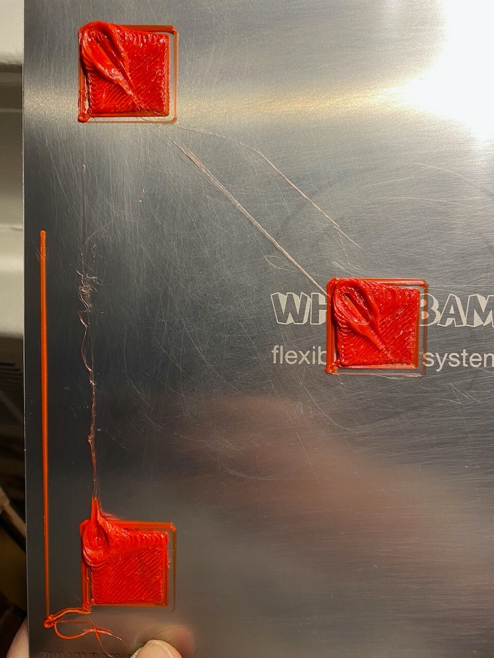
So when I printed this test off, there are pretty obvious slash marks across just two of the printed areas. Is this due to the test gcode being too generic for my Ender 3V2 settings? Top left and center.
And bottom left, the first square, seemed to be the victim of some horrible gloop dropping off the head, which I failed to witness as I printed this test off without watching.
So, for the slash marks anyway, is that something easy to correct for in the test? I used the bed levelling M420 S1 from my EEPROM, and left all other settings save for the bed size, as is.
That is the nozzle plowing along as it moves to it’s next print position.
You can Z-hop, or extrude a bit less(your first layer looks a bit over extruded for one reason or another), use monotonic infill, maybe, or even iron top layers, but for me, that marking is almost always internal, and doesn’t show much if at all on the final print of a real piece
The lower left is too close the middle looks like it might be a bit as well the uneven look it has. from the picture the right side looks thinner that the left. It might be calibration or a warped bed. The slash looks like it could be z hop the nozzle dragged for sure.
So the first thing I did, was use Jason’s handy setup script to turn down the temp when prepping. Also, did the ABL. 25 points worth. Then started the gcode from the test site, with numbers recommended for Ender 3V2.
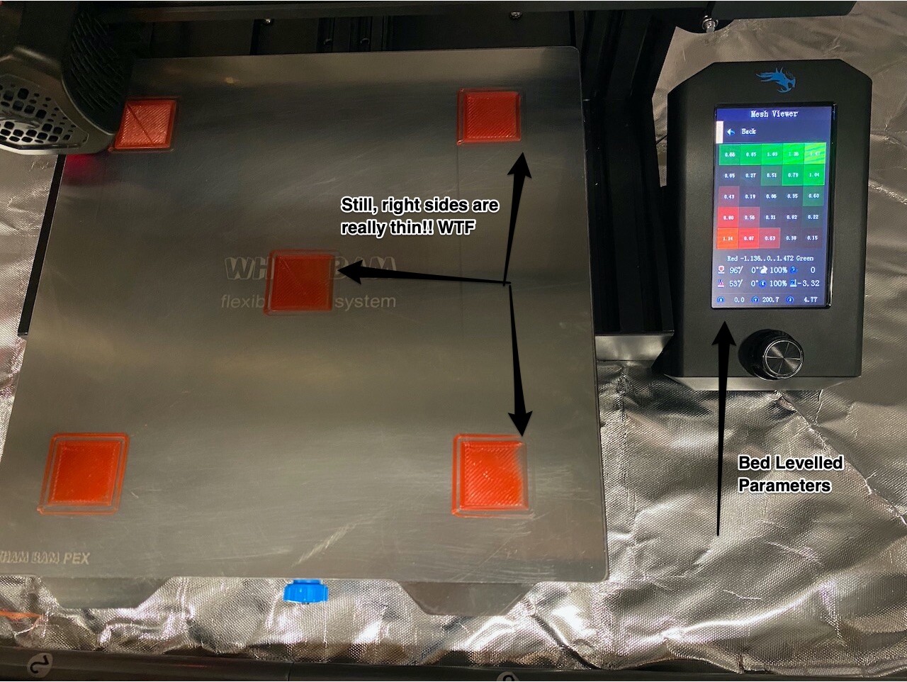
So now, after trying these prints, I am seeing a total fade on the right side of the squares, especially in the right hand side ones. What could be causing this? The first prints did not exhibit this, so it has to be something tinkered with in terms of adjusting this test to my printer.
A photo shows the thinning of everything on the right sides! Gah! I am so useless at this (for now). I have no clue why a printer would exhibit this kind of behaviour, where the left side is higher than the right, when the instructions are probably telling it to just lay down beads nice an even.
Some parameter seems off I guess. Anyone care to help me learn how to fix this kind of thing?
This is so frustrating. I changed the feedrate from 50mm/sec to 60 as my only change, and boom, complete and utter destruction? I am so chuffed. From nearly perfect to absolute crap in mere minutes!
It is a pretty simple bed. A piece of aluminum. Pretty flat. I glued on a magnet. Again, pretty flat. Then the Wham Bam slams itself home on that, and it’s a bed. So sure, it could be warped. But then, the ABL is showing me a mesh, and it is pretty flat. Nothing scary. But I understand, mils matter. So what I am faced with, is a bit of a monster. I can ignore these little intricacies of first layer madness if they really don’t matter. But it would be nice to know I am starting off on the right foot as they say.
Wow. I do not know what is going on there…
I feel your pain though.
Maybe back up to the beginning.
Is your gantry level with your frame and the bed level to that?
All the idler wheels snug?
Nothing physically changed there other than yes, a new clean surface to print on. So that mess had to be some software screw-up. I will try again tomorrow. Reset back to the defaults.
That bizarro lumpen mess of schlock has to be mangled gcode. If it is hardware, I am so screwed! To go from nearly perfect to that in 2 steps, does not bode well for the future!
Ok, is the BL touch straight? I don’t think that is what it is but I can’t figure out how the that could be like that in three points. One point is bed level. Three is something else. I think. Could the hot end be mounted off axis?
It is a challenge, albeit one I think I can handle. The usual problems vex me. I always get worked up when things go wrong, but as usual, sleeping on it, and then attempting to fix it in the morning usually works wonders. I am amazed at how quickly this takes me back to my early days of Z-80 8-bit computing, assembly language, and the TRS-80. Working with gcode is exactly like that!
The Bed is Level. I will investigate the rest of the print mechanism, and try and ID what the problem could be. Likely something in the hot-end where the extruded plastic is supposed to flow out properly. After my morning coffees I will attempt to debug this horror show!
The BLTouch is mounted with 2 screws and metal. I am not sure how that could be skewed. I will do an ABL sequence and examine the mesh it creates before any more prints, and after that, if that seems normal, I will examine the print head, although I am not sure there is anything to really see there. If it fails to print, and all my prints are toast I will be at the mercy of 3DPrinting to try and help me out of this.
I suspect bad gcode… but then again, such crazy puddling, and smashing, it was like Godzilla in Tokyo during that last run. Scary.
So in the morning, I re-did the gcode, eliminating most of the Jason start-up scripting, leaving a G29 to ABL with the nozzle set at 120, then boosting it to 200 before printing.
So it printed back to the original variants, pretty nice, but not perfect. The ONLY thing really jumping out here, is the right side of each square, from the skirt to the material laid down, is super thin. In a small region such as a square like these test squares, how can the material extruded be so different? It cannot be a bed issue, can it? How???
Uploaded a picture with the bed level mesh visible, and the damage. Interestingly, the worst square, bottom right, seems to be the one closest to zero compared to the other corners. But with ABL values fed to the printer, that should not matter right???
Last time we saw something weird like this, Ender 3V2 non level x gantry , it was cables interfering with the motion of the hot end assembly, but here…
I decided to re-think the whole BLTouch calibration. When I swapped out the Creality glass for the Wham Bam, I lost some thickness, so in that process, I hand tuned the Z-offset to an astounding 3.2 or something. So then, through this forum and others, I see there is a BLTouch calibration tool, called the Wombat. So I printed that out. The print seems near perfect. Who knows, I have no way of telling. I guess precision calipers would help, but probably not.
Anyway, this new tool should allow me to precisely set the Z-offset to ensure that that is truly on and not just my best guess. My best guess got me pretty far, but it is something at least for me to double check on.
Other than that, I have nothing to go on as far as why the right side of extrusions is thinner than the left when by formula, an extrusion between 2 points in space should maintain a consistent Z, unless of course the bed levelling numbers indicate a move. But with the moves on this machine being not so fine-grained, I cannot see that coming into play in such a small area, and so consistently. Even the tool skirt printed where the left was thicker and more defined than the right.
Woof. Got myself into a pickle with this new gear, and no real experience with the world of plastic extrusion.
Forgive me if you know and/all of this.
My understanding of BLTouch Z-offset is that that number is setting for where the BLTouch is mounted on the X-carriage. Once it is done, changing build plates should not matter. Mine is 3.775mm
I did mine, 170C nozzle / 70C bed, home Z-axis, then move down to Z = 0, check the nozzle distance from the build plate with my thinnest feeler gage(0.040mm, or thin paper) then adjust, Z-offset so I can just fit it in with reasonable resistance.
I did the similar calibration. I have no qualms about leaving my current setting alone, but I have nothing else to go on, as that is the only thing I have had to “hand-tune” or guess at, since that BL Touch install. So in the back of my mind, it is the only thing that could be “off”. If even by a .01 or something.
Still, it does not explain why the extrusions would have this difference between right and left sides. So, me, beating a dead horse!