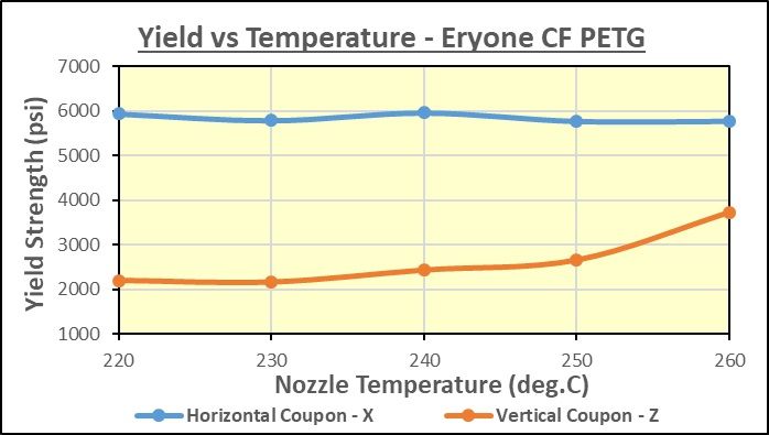
Not sure how I missed posting it, but a week ago or so I tested Eryone CF-PETG… Here are the results…
The horizontal (X-axis) strength was pretty flat regardless of temperature, but at 6000 psi max. it wasn’t as strong as Overture PETG with no carbon fibre!.. The vertical (Z-axis) was also significantly weaker than the plain PETG, until the temperature got to 260C, at which point it was basically equal… I was not impressed with the Eryone…
Yesterday and today I tested the French made Kimya PETG-CF, which is pretty pricey at $50 per 500g roll at Digitmakers.ca (it’s not easy to find), which puts it in the same price range as 3DXTech’s PETG-CF at $76 per 750g at the same store… I really liked this filament, finally I am seeing the X-axis strength bump up significantly more than straight PETG, into the same range as PLA… Here are the results…
At some point I hope to test the 3DXTech offering in CF-PETG, once my wallet recovers a bit!..
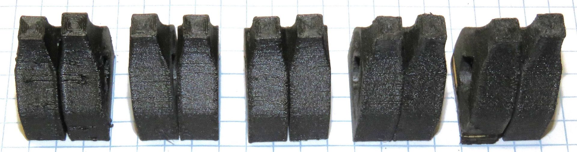
OH!.. One more thing… I took a closeup photo of the broken Z-axis coupons at various temperature, from 220-260C… Here they are, left to right… Click to enlarge…
You can clearly see that at 220C the layers are distinct and separate, and the hotter you go, the more melting and fusing that occurs between the layers… By the time you get to 260C, you really can’t see the layer lines any more… This shows why the strength in the Z-direction increases with temperature…
It is results like this that make me very glad I am putting in the effort… Today I tested the plain-jane version of Eryone PETG, in white… It is a fairly translucent colour compared to other whites I have seen, so I am guessing a minimum amount of pigment… Here are the results…
The results for the Carbon-Fibre filled version are in the previous post… Note that the vertical (Z-axis) is almost identical… However, the important thing is that the plain PETG version is as much as 30% stronger than the CF version in the horizontal (X-axis), where the carbon fibres are supposed to be “aligning with the extruded plastic” and therefore increasing the strength and stiffness… Well, not in my testing it didn’t… In fact this everyday Eryone PETG is the strongest I have tested so far along the printed strands!..
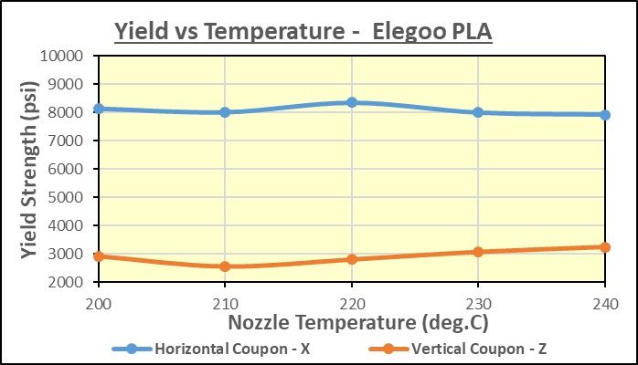
I decided to run a test on the Elegoo PLA that I bought for my 4-player Chess set… I had a bit of extra red, and here are the results…
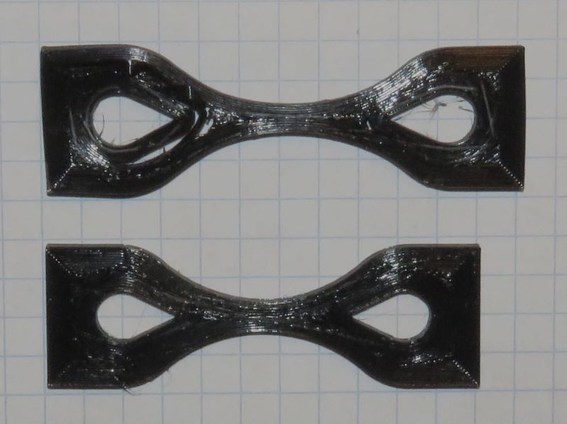
I have modified the coupons yet again, reducing the hole for a 5/16" pin instead of 3/8"… as I was still getting an occasional failure through the side of the eye, where my FEM analysis said the stress was high… I think the bending at that point as the coupon stretched was the reason, and reducing the diameter of the hole straightens out the stress lines there… The coupons are still giving the same values, but they are even more consistent, and I have not had any more fail except right where they should…
The Elegoo was typical for the Yield strength in the XY plane, and all 5 coupons stretched in the middle after they yielded… All the Z coupons broke cleanly right in the center… The layer adhesion was not as good as some other PLAs, but better than the wood-filled one… That may be a function of the colour, if I have enough of the blue, white and black left over I will test them at 220C (where the red was the strongest in the horizontal) to see if colour makes a difference…
I think there’s interest, at least I’m interested, and I’m sure most of us appreciate the effort you’re putting into this. None of the materials you have tested happen to be anything I use right now so while it is fascinating to compare it doesn’t have any direct value to anything I’m printing. I kind of wonder if that’s a similar situation for others on here which results in the crickets for response that you’re getting. (also I lurk far more than I post here so that doesn’t help)
I wonder if 3DPC would be able to send you some samples of their more popular filaments to test in order get some results that might apply to a wider audience at least as far as this forum is concerned.
I’m thinking PLA and PETG from the standard filament line, Canadian Made, Spektrum, and Matter 3D.
I don’t know if it’s possible to do a poll on here to gauge which filaments would be of most interest.
Then maybe start combining some of those results onto a single graph for each filament type to make it easier to digest and compare.
I’ve been following what you’re doing with interest but I haven’t seen anything that I would consider commenting on.
Once you build up a critical mass on each of the different materials, I’d be interested in seeing the distribution and the ranges.
My particular interest is in seeing the strength distribution of PETg as that’s what I’m using now for structural parts.
I would only use PLA for tchotchkes and the like so I’m not too interested in that material strength. I’m moving away from ABS as I go to all PEI print surfaces - I don’t want to have to make up ABS juice for adhesion.
I’ve done a bit of experimenting with Carbon Fibre, Nylon and Igus 151/180 filaments so if you generated some information on these, I’d be interested.
Sorry, I should have at least given you a like to say that I’ve been reading and appreciating what you’ve been doing.
Blair and Myke, thanks for your comments… It makes sense that unless I happen to test a filament somebody is using I won’t receive a comment… That is why I mentioned that if anyone wants a particular filament tested to send me enough to test (just over 100g, about 35m) and I would share the results here… I was in touch with 3DPC (through a Mod here), but they weren’t interested in my suggestion at the present time… I think they want more sophisticated testing, with stress/strain curves which I cannot supply with my equipment… All I can do is provide the maximum stress at failure (break or yield point), although I have now refined the coupons to get rid of corners, so that they always fail near the middle of the test section… My data is good, just not extensive enough… I am making bar charts of the XY and Z strengths of various materials, and will post them when I have enough data for them to be interesting…
I too have been watching in curiosity. In the absence of absolute standard testing where your results could be compared directly to another person testing too this will always be the case. It will only be useful if you touch upon a material someone reading uses.
I have a suggestion. Try testing other things other than materials.
It appears in earlier photos you might be using Arachne ? it might be interesting to compare it to classic wall generator, does this effect strength? I think Classic is stronger but Arachne is more efficient. Based upon gut feeling…
Rather than material maybe settings where as long as the material and printer are consistent the results are valid for all.
Sorry, I don’t know what Arachne is… I use Cura to generate my coupons, which I design in TinkerCad… The walls are thick enough to print all stressed areas at 100%…
I have seen lots of data generated, eg. Stefan at CNC Kitchen, but he seems to select one temperature, whereas I use a range of temperatures for each material, as I wanted to generate additional data I have not seen elsewhere… I have fine-tuned the coupon design to eliminate the occasional failure I had through the eye, or that might have been due to the corner adjacent to the test section… I checked the coupon designs as I progressed to make sure they were not having a significant effect on the results… The results I am getting now are very consistent…
Arachne is a perimeter generator, it is used in many slicers. UltiMaker designed it. (Cura, PS, Bambu, super) It changes the way the walls are calculated. It creates variable wall thickness it is default in Cura5. It also opens gaps sometimes. It shouldn’t but does.
It looked like to me you have these gaps they appear in the photos and the separation at permitters could or not be a result.
My point is there are way too many variables to have a standardized test your work like Stefans, Thomas, and many others cannot be compared to each other.
This means your testing compares to itself. I am certain you are consistent that is why I am suggesting what I am. If you take that consistency you could determine what settings increase or decrease strength. This doesn’t matter what filament and applies to everyone using that slicer. Perhaps everyone using that setting.
Nobody is doing that either although slant maybe but your tests are more logical I think anyway.
I see what you are getting at… My coupons have improved a lot, I no longer am getting separations between the perimeters, and have virtually eliminated the infill except a few small areas where there is little stress… This has improved the consistency even more, I am getting virtually no “unusable” data now… All coupons break near the center of the thin test section now, well away from any stress risers… I have adjusted the cross sectional area of the thinnest point to put the data near the middle of the range of my force gauge, so unless I find something really strong I won’t run out of range now… This means just over twice the area on the “Z” coupons…
I plan to eventually concentrate on carbon-fibre filled materials suitable for outdoor use, that can be printed on a conventional, commonly available printer such as my Ender 5 S-1… ie a heated bed and no enclosure… I think that means a lot of testing of PETG-CF products… I will be varying the settings in that testing, changing not only the temperature as I am doing now, but also the nozzle diameter and layer thickness, to try and optimize the strength… It should be interesting!..
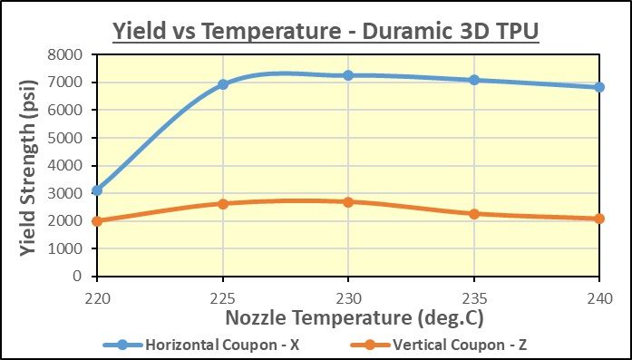
I received a sample of Duramic 3D TPU from a reader, and ran the tests on it… twice!.. The first couple of coupons were OK, but as I got deeper into the (re-rolled) sample, it was wet, and the coupons became rough, pebbled, with a frosted appearance, and the strength dropped… I dried the filament for 12 hours at 50-55C, and then it was fine… Here are the results for the dried filament…
There was a huge increase in strength between 220C and 225C, after which it leveled off… At 220C, the horizontal coupons failed because the layers were separating across the coupon, particularly where they were bonded to the sides of the “eye”… At 225C and above, that did not occur, even at maximum load… The peak strength occurred both in X and Z at 230C, and all samples had a high gloss…
Boy, does this stuff stretch!.. I increased the travel rate to 20mm/min. (from 5), and the stronger horizontal coupons stretched 170mm in 8.5 minutes before snapping… That is to say, to over 4 times their original length!.. Elastic materials certainly do not follow the rules, as when you take into account how small the section was (about half size in width and height), when they failed the stress was about 4 times that shown in the graph above (ie approaching 30,000 psi)… Of course that is not how you do it, but it shows why things like tennis racquet strings can stand the tension that they can, by stretching…
The numbers I use to create my graph are the maximum (peak) force reached before there is no further increase, which can either be at break, or when the coupon starts to stretch and weaken, as you would have with most plastics then they are “necking down”… The force gauge I use can be set to record the peak force, which is what I do… I report the “Ultimate Yield Strength”, which means the maximum force the coupon ever attains… and the maximum load it can support for a given starting area, which is what we really care about…
Yes, the cross sectional area decreases as the coupon stretches, and as an example, if the area is only 1/4 of what it started at, the instantaneous stress at that point in time would be 4 times what it would be when calculated using the starting area… The same thing occurs, to a minor degree, with any material… Using the original area gives the “Engineering Stress/Strain Ratio” (aka Nominal Stress), if you use the instantaneous cross section, you get the “True Stress/Strain Ratio”…
I have no practical way to measure the constantly changing area during the test… If I had the equipment to measure the elongation in real time during the test, I could plot the Nominal Stress/Strain curve, which will tell you more about the material, for sure, but I don’t… Although the stress (force per unit area) increases as an elastic material stretches, it does so at very large amounts of strain (extension per unit length), so the elastic (Young’s) modulas “E” is actually very low… Young’s Modulas is a measure of the “stiffness” (or elasticity) of a material, and is well beyond my simple measurements…
wow, I know it would stretch some but had not expected it to be that much.
Also interesting is how low the breaking point of the z axis coupons are compared to most of the other types of filament you have tried, though the the x is close to many of the common pla/petg types that you have tested.
do you have photos of the TPU coupons after they broke?
thanks
Here are the coupons from the TPU testing… First a horizontal (X) one at 220C (wet), before and after testing… Note the delamination, which did not occur above 225C…
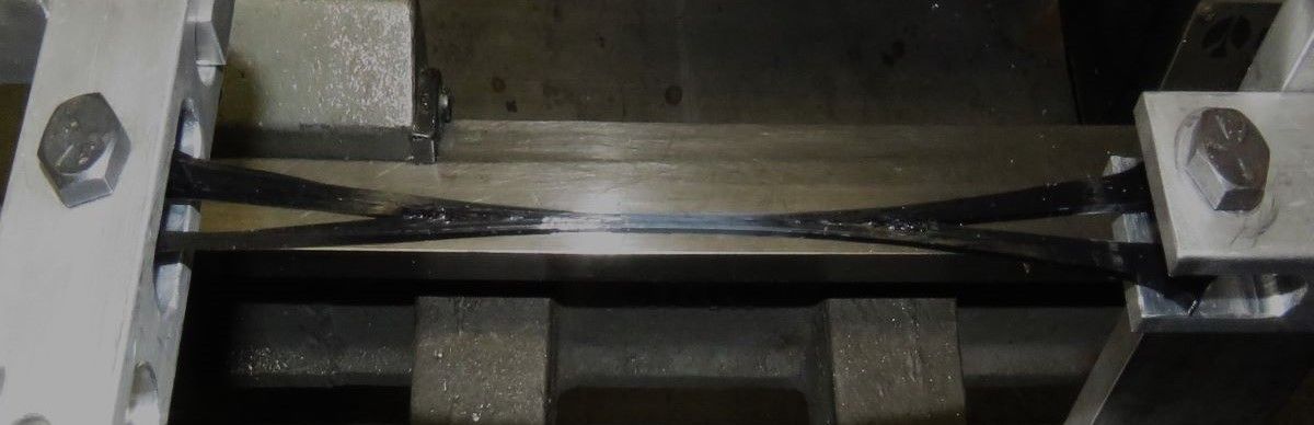
The next is one on the torture rack, again a horizontal one…
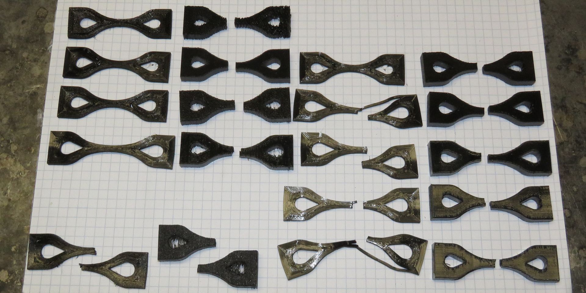
Here are all the Coupons after testing… The left column is horizontal (wet), second column is vertical (wet), third column is horizontal dry, right column is vertical dry…
The top row (L only) is at 210C, horrible finish, virtually no bonding… Second row at 220C, third at 225C, fourth at 230C, fifth (R only) is at 235C, and the bottom row is at 240C… Note the rough finish and stringing on the wet vertical coupon at 240C… That is when I decided I had to dry the filament…
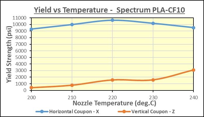
I got a sample pack of Spectrum (Polish) filament, with 5 different plastics, all with a carbon fibre fill… The first one I tested was the PLA-CF10, which as the name suggests has 10% carbon fibre content… Here are the results, plotted vs temperature… Printed with a 0.4mm nozzle, at 0.25mm layer height and 0.40mm line width… pretty much standard settings for CF…
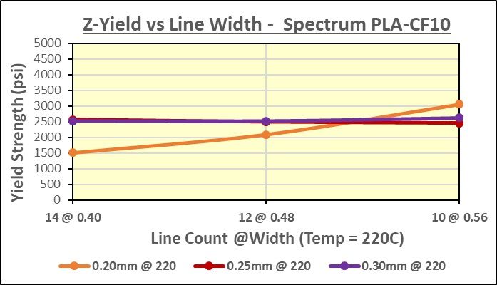
This material is a bit stronger than any other PLA I have tested in the horizontal (X) direction, but quite weak in the vertical (Z) direction… The layer to layer adhesion is not great… I was curious about how layer height and line width affected the strength, so I did some more tests… First of all, the horizontal (X-axis) strength does not appear to change when these are varied, total variance was within 3%… However, the layer to layer adhesion changed quite a bit… All the tests were done with a 0.4mm nozzle at 220C… above which the horizontal strength drops… Here is what happens when you change the line width… 0.40mm is 100% of nozzle diameter, 0.48mm is 120%, and 0.56mm is 140%… The number of walls in the test section (0.56 x 0.56mm) is also given, along with the line width, in the X-axis labels…
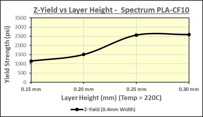
Note that with the 0.25mm and 0.30mm layer height there is virtually no change in the yield strength in Z as you change the wall thickness… However, with the 0.2mm layer height, increasing the wall thickness greatly improved the strength… With this in mind, I then tried four different layer heights, again at 220C with a 0.40mm line width, and got the following results…
It is quite obvious that as the layer height is increased above 0.20mm, the layer to layer adhesion increases a lot… I’m guessing this is why a 60% of nozzle diameter minimum layer height is recommended for carbon fibre filled filaments… Possible the inclusions in the matrix from the particles requires a thicker layer for optimum strength… One wonders if the same thing applies for wood filled, silk, or matt filaments, which tend to have weaker layer adhesion?..
That’s really interesting about the 60% of nozzle diameter for layer height. I hadn’t heard that before. I’ll definitely be trying that for both my wood and carbon filaments since I’ve been pretty disappointed in their layer adhesion.
I’ve also been finding that having adaptive layer height in Cura turned on can produce pretty bad surface finish with my carbon petg on the layers that were thinner than the default 0.2mm so I have been turning that off lately. Sounds like having it turned on was also likely causing weaker layers.
I have seen that in more than one location, but the company that really makes a point of it is 3DXTech… They say 60% of the Nozzle diameter is the ideal layer height, and to use a layer height of 0.25mm or higher… They also state a minimum 0.4mm nozzle diameter, and a hardened steel nozzle, of course…
I am curious if it is the ratio of the laid down line that should be 60% (ie 60% as high as wide), or if there is an advantage to using a wider line and then an even greater layer thickness… For example, if you are using a 0.4mm nozzle with a line width of 0.5mm (125% of the diameter), should you use a layer height of 0.25mm (50%) or 0.3mm (60%), and would either of those have better layer adhesion than the 0.25mm layer with a 0.4mm width?.. Alternately, would using a 0.6mm nozzle with a 0.36mm layer height (60%) be even better?.. More testing required…
Blair, if you find an improvement in layer adhesion by increasing your layer height, please report it here…